Philips 34PW862H User Manual
Page 6
H
OOKING
UP
THE
T
ELEVISION
T
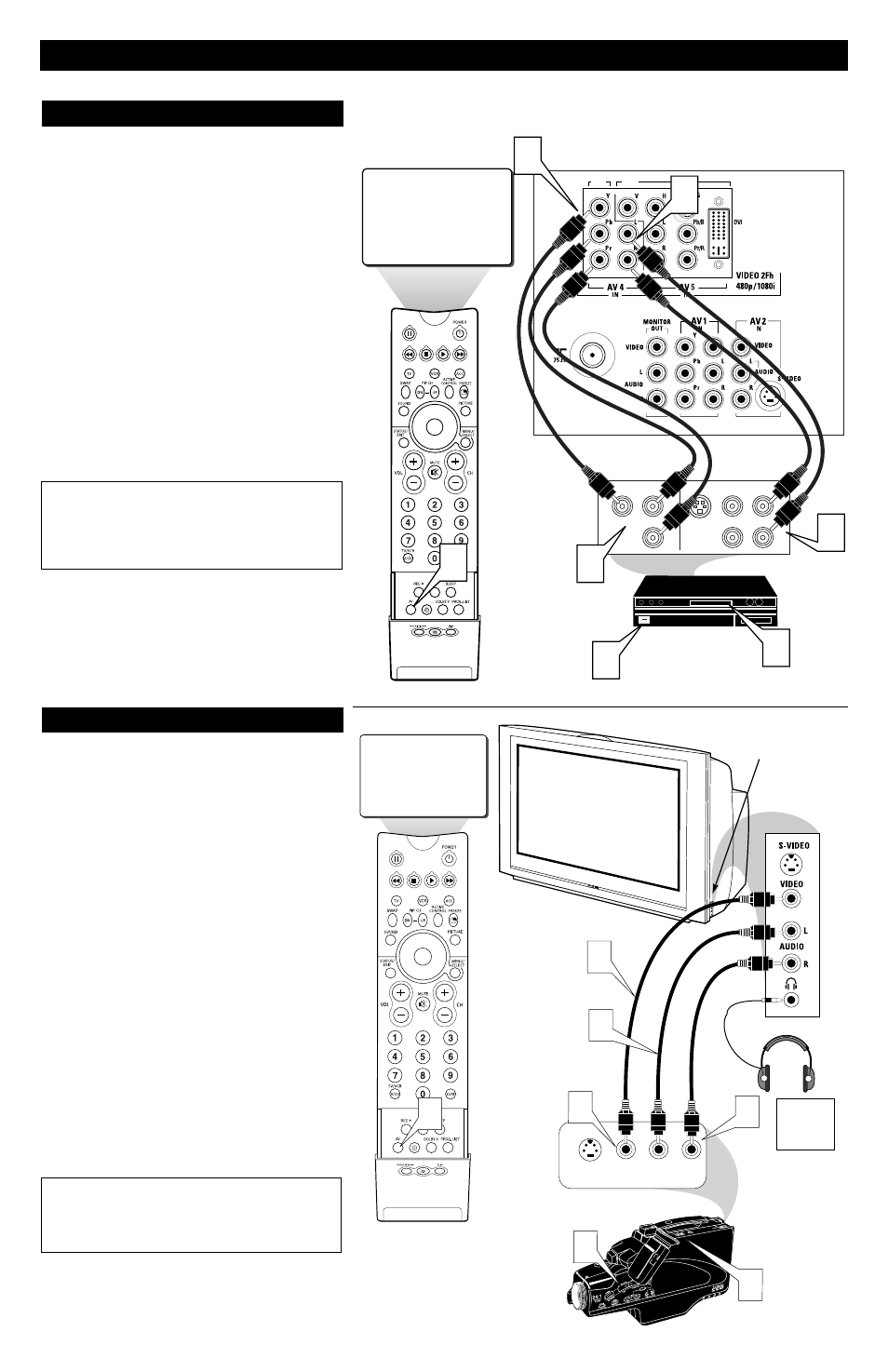
he AV4 Input Jacks provide High Definition Video Inputs at
1080i or 480p, for accessories like a HD Receiver and Digital
DVD Players. Using the color difference signals (Pb, Pr) and the
luminance (Y) signal will improve color bandwidth information.
1
Connect the Component (Y, Pb, Pr) Video OUT jacks
from the DVD player (or similar device) to the (Y, Pb, Pr)
AV4 IN(put) jacks on the TV.
2
Connect the red and white AUDIO CABLES to the
AUDIO (left and right) OUT(put) jacks on the rear of the
accessory device to the Audio (L and R) AV4 IN(put) jacks
on the TV.
3
Press the AV button on the remote control repeatedly to
tune to the AV4 channel.
4
Turn the TV and the DVD (or digital accessory device)
ON.
5
Press the PLAY button on the DVD (or digital accessory
device) to view the program on the television.
U
SING THE
AV 4 I
NPUT
J
ACKS
HD1
HD2
AV4
3
S-VIDEO
OUT
OUT
OUT
L
R
AUDIO
VIDEO
COMP VIDEO
Y
Pb
Pr
2
1
4
5
1
2
JACK PANEL
ON BACK OF TV
JACK PANEL
OF DIGITAL DEVICE SUCH
AS A DVD PLAYER
EQUIPPED WITH
COMPONENT VIDEO
OUTPUTS
Note: If the AV4 channel is tuned and no signal con-
nection present, the screen could jump or flash.
AUDIO IN
(RED/WHITE)
COMPONENT
VIDEO
CABLES
NOTE: This television is designed to accept high definition sig-
nals 1080i and 480p as specified by the Electronic Industries
Association standard EIA770.3. Digital devices from different
manufacturers have the possibility of differing output standards
which my cause difficulties for the television to properly dis-
play.
T
his television has input jacks conveniently located on the side
of the cabinet. These jack are for easy hook-ups (without hav-
ing to move around to the back of the TV) for cameras, gaming
units, and other accessory devices that wouldn’t be connected
permanently. Follow the easy steps below to connect your acces-
sory device to the SIDE Input Jacks located on the right side of
the TV.
1
Connect the VIDEO (yellow) cable to the VIDEO IN
jack on the side of the TV.
2
Connect the AUDIO (red and white) cables to the
AUDIO (left and right) IN jacks on the side of the TV.
3
Connect the VIDEO (yellow) cable to the VIDEO OUT
jack on the back of the camera (or accessory device).
4
Connect the AUDIO (red and white) cables to the
AUDIO (left and right) OUT jacks on the rear of the cam-
era (or accessory device).
5
Turn the camera (or accessory device) and the TV ON.
6
Press the AV button on the remote control repeatedly to
tune to the AV3 channel.
7
With the camera (or accessory device) ON and a prere-
corded tape (or other media depending on type of accesso-
ry device being used) inserted, press the PLAY button to
view the tape on the television.
U
SING THE
SIDE AV 3 I
NPUT
J
ACKS
AV3
S-VIDEO
VIDEO
AUDIO
LEFT RIGHT
3
7
5
AV3
1
4
6
2
VIDEO IN
(YELLOW)
NOTE: The S-Video Cable can be used in place of the Yellow
Video cable shown in this diagram. If your camera or accessory
device has a S-Video output jack, connecting the video signal
through the S-Video jack will reproduce the video signal with
greater quality.
AUDIO IN
(RED &
WHITE)
Jack Panel of
Camera
or External
Accessory Device
SIDE (AV 3) Input Jacks
Located on the Side of
the Television Cabinet
The SIDE
JACKS also
contain a
HEADPHONE
JACK.
6