Round, Ssembly – Broilmaster BL48G-1 User Manual
Page 17
B101586-1-1011
Page 17
i
n
-g
round
p
oSt
A
SSEmbly
3.
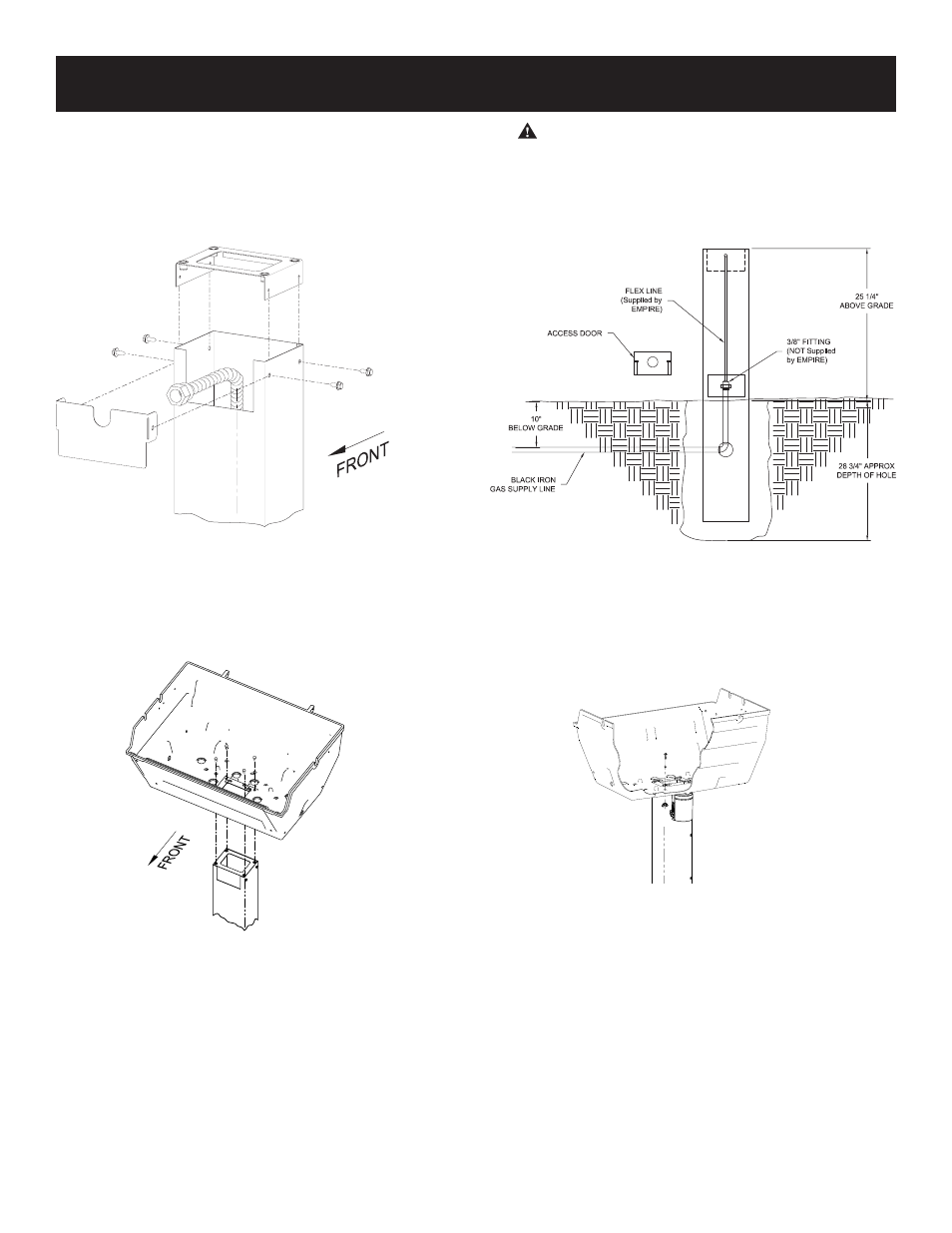
For R3 Series Grill Heads: Slide the Post Cover Plate onto the
front of the post. Slide the Upper Bracket onto the post. Secure
the Post Cover Plate and Upper Bracket to the top of the square
post using four #10 – ½ screws. See Figure 3.
For Grill Heads other than R3 Series: Slide the Upper
Bracket into the post. Secure the Upper bracket to the top of
the square post using four #10 – ½ screws. See Figure 3.
Figure 3
4. Place the grill bottom on top of the post and secure the grill bottom
to the post by placing four ¼-20 x ¾ Hex head screw in the thread-
ed inserts that are in the upper bracket. See Figure 3.
Note: Grill top comes assembled with to the bottom. For ease
of assembly, remove grill top.
Figure 4
5. Arrange with your local gas company or licensed contractor to
have a gas supply line connected to the inlet of the stainless
steel flex tube assembly. The gas supply must have a shutoff
valve that is close to the post in case of emergency and must
be shutoff when the grill is not in use. See Figure 5
The grill and its individual shutoff valves must be disconnected
from the gas supply piping system during any pressure testing
of that system at test pressures in excess of 1/2 PSIG. The
grill must be isolated from the gas supply piping system by
closing its individual manual shutoff valves during any pres-
sure testing of the gas supply piping system at test pressures
equal to or less than 1/2 PSIG.
WARNING: DO NOT SUPPLY LP GAS TO A GRILL DE-
SIGNED FOR NATURAL GAS OR NATURAL GAS TO A
GRILL DESIGNED FOR LP GAS.
Gas leak tests should be completed as directed in the grill
Owner’s Manual.
Completely fill remaining hole with soil.
Figure 5
6. Attach the grease cup bracket assembly to the bottom of the
grill casting and fasten with #10-24 x 3/4” bolt, 9/32 ID x 5/8
OD washer, and #10-24 wing nut. See Figure 6.
Use only the supplied grease cup or noncombustible contain-
ers for the grease cup (aluminum or tin cans). DO NOT use
combustible containers such as paper or Styrofoam cups.
Figure 6
7. Continue assembly as directed by the Owner’s Manual pack-
aged with the grill head.