Bunn CWTF TWIN-APS User Manual
Page 23
Page 23
SERVICE (cont.)
10737 120800
5. Check for continuity between the black wire re-
moved from the limit thermostat and the black
insert on the terminal block. with the tank heater
switch in the "ON" upper position. Continuity should
not be present in the "OFF" lower position.
If continuity is present as described, the tank heater
switch is operating properly.
If continuity is not present as described, replace the
tank heater switch.
Removal and Replacement:
1. Shut off and disconnect the incoming water sup-
ply to the brewer.
2. On automatic brewers gently remove the fill tube
from back of fill basin.
3. Remove the tank inlet fitting securing fill basin the
tank lid. Remove fill basin and gasket. Set all three
parts aside for reassembly.
4. On brewers with faucets, disconnect the water
supply to coil assembly and remove the tube from
the tank to the faucet.
5. Remove sprayhead and hex nut securing spray-
head tube to the hood. Set aside for reassembly.
6. Disconnect the wires on the limit thermostat and
the tank heater and the control thermostat (early
models).
7. Gently pull the thermostat sensor and grommet
from the tank lid.
8. Insert a tube to the bottom of the tank and syphon
ALL of the water out.
9. Gently reinstall the thermostat sensor and grom-
met in the tank lid.
10. Remove the two #8-32 screws securing the tank
assembly to the hood.
11. Lift tank and components out as an assembly and
set aside for reassembly.
12. Disconnect the two black wires from the tank
heater switch.
13. Remove the plastic facenut, hex facenut and the
switch indicator/guard bracket that secures tank
heater switch to the rear of the brewer. Remove
switch and discard.
14. Insert new tank heater switch through the hole in
the upper left rear of the trunk and secure with
switch indicator/guard bracket, hex facenut and
plastic facenut.
15. Reconnect the two black wires the tank heater
switch terminals.
16. Set tank assembly inside the hood on mounting
brackets and secure with two #8-32 screws.
17. Reconnect the wires to the limit thermostat, tank
heater and the control thermostat. Refer to limit
thermostat, tank heater and control thermostat
sections in this manual when reconnecting wires.
18. Brewers with faucet reinstall the faucet tube and
reconnect the water supply tube to the coil assem-
bly.
19. Secure the sprayhead tube to the hood using hex
nut.
20. Install sprayhead.
21. Install fill basin, inlet gasket and secure to tank lid
with tank inlet fitting.
22. Carefully install water fill tube into the back of the
fill basin.
23. Reconnect and turn on the incoming water supply.
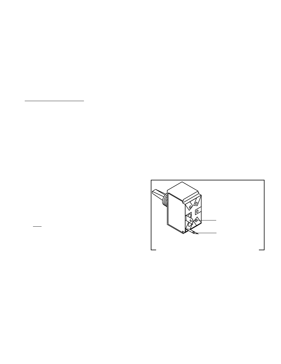
24. Refer to Fig. 18 when reconnecting the wires.
P1135
FIG. 18 TANK HEATER SWITCH TERMINALS
BLK to Limit Thermostat
BLK to Terminal Block
(Black Insert)