Bunn CWTF TWIN-APS User Manual
Page 22
Page 22
SERVICE (cont.)
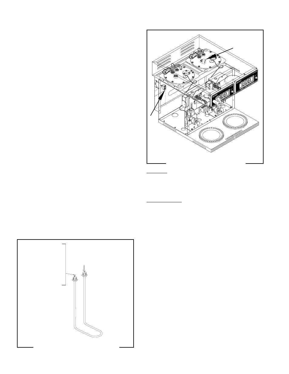
FIG. 16 TANK HEATER TERMINALS
P1239
Location:
The tank heater switches are located on the rear of
the brewer on the upper left and right side of the trunk.
Test Procedure:
1. Disconnect the brewer from the power source.
2. Disconnect the black wire from the limit thermo-
stat.
3. With the tank heater switch in the "ON" position
and with a voltmeter, check the voltage between
the black wire removed from the limit thermostat
and the red wire on the tank heater. Connect the
brewer to the power source. The indication must
be:
a) 240 volts ac on three wire 120/240 volt models.
b) 200 volts ac on two wire 200 volt models.
c) 240 volts ac on two wire 240 volt models.
d) 230 volts ac on three wire three phase 230 volt
models.
4. Disconnect the brewer from the power source.
If voltage is present as described, proceed to #5.
If voltage is not present as described, refer to the
Wiring Diagrams
and check the brewer wiring har-
ness.
TANK HEATER SWITCH
FIG. 17 TANK HEATER SWITCHES
P2197
10737 12800
TANK HEATER (Cont.)
6. Remove sprayhead and the hex nut securing the
sprayhead tube to the hood. Set aside for reas-
sembly.
7. Remove the eight #8-32 nuts securing the tank lid
to the tank.
8. Remove the tank lid with limit thermostat, spray-
head tube, tank heater, coil assembly and control
thermostat w/bracket (early models only).
9
Remove the two hex nuts securing the tank heater
to the tank lid. Remove tank heater with gaskets
and discard.
10. Install new tank heater with gaskets on the tank lid
and secure with two hex nuts.
11. Install tank lid with limit thermostat, sprayhead
tube, tank heater, coil assembly (brewers with
faucet) and control thermostat with bracket (early
brewers only) using eight #8-32 hex nut.
12. Reconnect the inlet and outlet water lines to the
faucet coil assembly.
13. Secure sprayhead tube to hood using a hex nut.
14. Install sprayhead.
15. Reconnect the wires to the limit thermostat, tank
heater and control thermostat. See limit thermo-
stat and control thermostat sections in this manual
when reconnecting wires.
16. Install fill basin (4), secure with tank inlet fitting (2)
and gasket (3). Insert water supply line (5) through
grommet in fill basin (4).
17. Refer to Fig. 16 when reconnecting the tank heater
wires.
BLK to Control Thermostat
(Brewers w/out faucet)
BLK to Fuse (Brewers w/
faucet)
RED to Terminal Block
(RED Insert on 120/240
Three Wire Models or
200V Two Wire Models,
240V Three Wire
Models or 240V Two
Wire Models)