B&B Electronics DELTA Temperature Controller DTB Series User Manual
Page 5
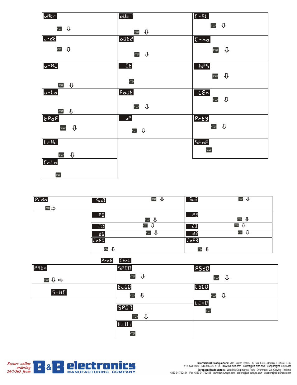
4
Time setting for valve from
full close to full open. (Display when
valve control is ON)
Press
Display and adjust output value
of 1st output group
(Display in PID control mode and manual
RUN mode)
Press
ASCII, RTU communication
format selection
Press
Press
Valve Dead Band setting.
Press
(Display when valve control is ON)
Display and adjust output value
of 2nd output group
(Display in dual loop PID control mode and
manual RUN mode)
Press
Communication address
setting
Press
Upper-limit regulation of
valve output with feedback to
controller. (Display when valve
signal feedback function is ON)
Press
In case of using an external CT,
the controller displays the current
value being measured by CT, if
the control output is ON
Press
to return to set target temperature
Communication baud
rate setting
Press
Lower-limit regulation of
valve output with feedback to
controller. (Display when valve
signal feedback function is ON)
Press
Valve output with feedback.
(Display when valve feedback
function is ON)
Press
Data length setting
Press
Press
Regulate temperature
deviation value
DA value feedback of valve.
(Display when valve feedback
function is ON)
Press
Back to target temperature
Parity bit setting
Press
(The setting display when analog output)
Press
Regulate upper-limit of analog
output value
Stop bit setting
Press to return input type setting
Press
Regulate lower-limit of analog
output value
(The setting display when analog output)
to return to auto-tuning mode
* 1 Scale = 2.8uA = 1.3mV for tuning output value
PID mode selection: any one of 4 groups PID modes (n=0~3) can be selected. When n=4, program will automatically select 1 group PID that is
most useful for target temperature.
Select n=0~4 to
decide PID mode.
0~3 groups PID
Press
PID setting: n=0.Press
PID setting: n=3.Press
Proportion band setting: n=0.
Press
Proportion band setting: n=3.
Press
Ti setting: n=0. Press
Ti setting: n=3. Press
Td setting: n=0.Press
Td setting: n=3.Press
Integral deviation setting: n=0.
AT setting.
Press
back to PID deviation setting
Integral deviation setting: n=3.
AT setting.
Press
back to PID deviation setting
Pattern and step editing selection: edit
in
parameter. The following display is the example operation of pattern No. 0.
select OFF
Press
Select desired editing pattern
number
select number
Edit temperature of step No. 0
of pattern No. 0
Press
Select actual step No. when
program control is executing
Press
Exit p
attern and step editing selection
Switch to and continue setting
Edit time of step No. 0 of
pattern No. 0, unit is hh.mm
Press
Set additional execution cycle
number(0 to 99)
Press
Set step No. 07 in order
Press
Edit temperature of step No. 7
of pattern No. 0
Set link pattern, OFF indicates
the program end
Press to return pattern No. editing
mode
Press to set actual step No.
Edit time of step No. 7 of
pattern No. 0, unit is hh.mm