Liebherr LTM 1160-5.1 User Manual
Page 8
9
8
LTM 1160-5.1
LTM 1160-5.1
LSB 3
LSB 1
CAN-Bus
3a
8
1
2
2a
1a
22
LSB 1
15
6
5
LSB 1
18
16
17
7
23
3
CAN-Bus
LSB 4
CAN-Bus
20
19
4
11
LSB 2
4a
14
13a
12
9
21
21
10
13b
7
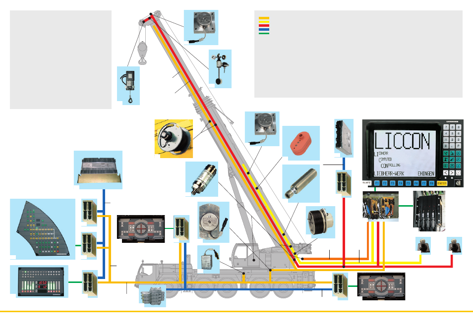
Tilt angle sensor for automatic leveling
8
Rotation sensor in slipring unit
9
Connection to Liebherr system bus (LSB 1, 2, 3, 4)
10
LICCON central unit
11
LICCON monitor in crane cab
12
Length sensor and cable drum/energy cable for
interlocking gripper/telescopic boom
13 a Inductive sensors (6 x)
13 b Track sensors (2x)
14
Angle sensor on boom pivot section
15
Cable drum for items 16, 17, 18
16
Wind sensor
17
Hoisting limit switch
18
Angle sensor
19
Input/output module for electronic control of diesel engine
(superstructure), air flap, fan clutch, exhaust flap valve
20
Injection pump control – Liebherr diesel engine
(superstructure)
21
Control sensor
22
Pressure sensor (4 x) for output management and LMB
(safe load indicator)
23
Valve for active rear-axle steering
Legend:
LSB - Liebherr system bus 1
LSB - Liebherr system bus 2
LSB - Liebherr system bus 3
CAN - Busses
SCI - Serial Communication Interface
1 Input/output module for control of the suspension, Liebherr
diesel engine, automatic transmission, control functions,
compressed air monitoring for brake functions
1a Instrument panel key unit in driver’s cab
2 Input/output module for differential locks, display functions
2a Instrument panel key unit in driver’s cab
3 Input/output module for outrigger system - right
3a Control unit for outrigger system - right
4 Input/output module for outrigger system - left
4a Control unit for outrigger system - left
5 Input/output module for engine brake, cruise control,
speed holder, electronic control of diesel engine
(right steering column switch) and automatic transmission
6 Control of Liebherr diesel engine (chassis) and
automatic transmission
• Electric and electronic components are interconnected by
the latest data bus transmission technology
• Instead of the traditional electric wiring, data transmission
to the individual function blocks is performed digitally along
just a few data cables, thus improving reliability thanks to
a much-reduced number of contacts
• Bus systems of Liebherr’s own manufacture (LSB), specially
suited to mobile crane requirements
• Diesel engine and automatic transmission are controlled by
a CAN data bus. All-electronic driveline management reduces
fuel consumption and exhaust emissions
• The chassis and crane electrical systems and all cockpit
functions and the outrigger and boom sensor systems are
interconnected by 4 Liebherr system bus lines
• Control of the function blocks is by I/O modules programmed
by the Liebherr system bus lines. The control intelligence is
integrated into the central LICCON unit
• Comprehensive diagnostic facilities, quick fault localization,
operating error display
• Programs for functional test of keyboard and display unit
and for testing the engine and transmission management
control units, additional Liebherr brake system, hydraulic
fan, hydraulic suspension and outrigger control panels
• This new data bus technology greatly enhances the
functionality and efficiency of the mobile crane