Liebherr LTM 1160-5.1 User Manual
Page 4
9
4
LTM 1160-5.1
LTM 1160-5.1
700
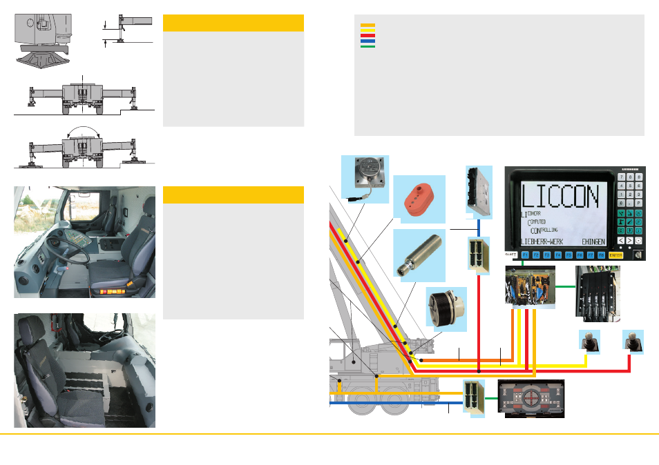
CAN-Bus
LSB 4
CAN-Bus
20
19
4
11
LSB 2
4a
14
13a
12
9
21
21
10
13b
• Variable support base width
Outriggers retracted
Support base area 5.0 m x 7.9 m
Support base area 7.5 m x 7.9 m
• Fixed support pads with splash guard
for protection against dirt
• Support jack extension range up to 700 mm
• Self-leveling of the outriggers, fully-automatic leveling of the
crane by pushbutton during the supporting procedure
• 2 x 9° lateral inclination of crane chassis and superstructure
• Control panels at either side of the chassis with foil-covered
keyboard and electronic angle indicator, pushbuttons for
ENGINE/START/STOP and speed control are illuminated
and lockable
• Operation of the outrigger system in accordance with the
accident prevention regulations
• Illumination of the support area by 4 built-in lights
Supporting crane on outriggers –
quick, convenient and safe
• Modern, comfortable operator’s cab of highly efficient,
convincing design, corrosion-resistant sheet steel
construction, cataphoretic dip-primer coating, resilient rubber
front mountings, hydraulic damping at rear, sound and heat
absorbent interior paneling
• Safety glass all-round, sunproof green-tinted windshield and
side windows for heat absorption, electric window lifters
• Ergonomically correct arrangement of controls and displays
for safe and convenient handling for long periods
• Digital display and key-panel units interconnected with the
functional blocks by data bus technology
• Air-sprung driver’s seat with pneumatic lumbar
support and head restraint
• Steering wheel adjustable for height and angle
• Heated, electrically adjustable outside mirrors
• Seat belts for driver and co-driver
• 3 windshield wipers with automatic wipe/wash system and
intermittent-wipe setting
• Delayed switch-off of interior lighting
• Various storage shelves and compartments
• Preparation for radio
Comfortable, highly efficient
operator’s cab
7
Tilt angle sensor for automatic leveling
8
Rotation sensor in slipring unit
9
Connection to Liebherr system bus (LSB 1, 2, 3, 4)
10
LICCON central unit
11
LICCON monitor in crane cab
12
Length sensor and cable drum/energy cable for
interlocking gripper/telescopic boom
13 a Inductive sensors (6 x)
13 b Track sensors (2x)
14
Angle sensor on boom pivot section
15
Cable drum for items 16, 17, 18
16
Wind sensor
17
Hoisting limit switch
18
Angle sensor
19
Input/output module for electronic control of diesel engine
(superstructure), air flap, fan clutch, exhaust flap valve
20
Injection pump control – Liebherr diesel engine
(superstructure)
21
Control sensor
22
Pressure sensor (4 x) for output management and LMB
(safe load indicator)
23
Valve for active rear-axle steering
Legend:
LSB - Liebherr system bus 1
LSB - Liebherr system bus 2
LSB - Liebherr system bus 3
CAN - Busses
SCI - Serial Communication Interface
1 Input/output module for control of the suspension, Liebherr
diesel engine, automatic transmission, control functions,
compressed air monitoring for brake functions
1a Instrument panel key unit in driver’s cab
2 Input/output module for differential locks, display functions
2a Instrument panel key unit in driver’s cab
3 Input/output module for outrigger system - right
3a Control unit for outrigger system - right
4 Input/output module for outrigger system - left
4a Control unit for outrigger system - left
5 Input/output module for engine brake, cruise control,
speed holder, electronic control of diesel engine
(right steering column switch) and automatic transmission
6 Control of Liebherr diesel engine (chassis) and
automatic transmission