Multi variable boom configuration system – Liebherr LTM 1400-7.1 User Manual
Page 4
PN 1400-7.1 DEFISR.fh11 24.07.2007 10:48 Uhr Seite 4
Probedruck
C
M
Y
CM
MY
CY CMY
K
4
9
LTM 1400-7.1
LTM 1400-7.1
10 m
20 m
30 m
40 m
50 m
60 m
70 m
80 m
90 m
100 m
110 m
120 m
130 m
T/TY
TF / TYF
TN / TYN
600
0 m
38°
38°
• Modern driver’s cab of outstanding functionality and
convincing design. Corrosion resistant sheet steel version,
cataphoretic dip-primed, front section mounted on shock
absorbers, rear damped hydraulically, internal sound and
heat absorbing panelling
• Safety glas all-round, greenish tinted front and side windows
for heat insulation, electric window lifters
• 3 automatic windscreen washers/wipers with intermittent
control
• Heated and electrically adjustable outer rear mirrors
• Air-cushioned driver’s and co-driver’s seat with headrests,
driver’s seat with pneumatic lumber support
• Safety belts for driver’s and co-driver’s seat
• Height and inclination adjustable steering wheel
• Standardized, digital operating and control instruments
arranged ergonomically for safe and convenient handling,
arranged operator-friendly in a half-round shape
• Digital display and keyboard units interconnected with the
functional blocks by data bus technology
• Additional heater with engine preheating
Comfortable driver’s cab of
outstanding functionality
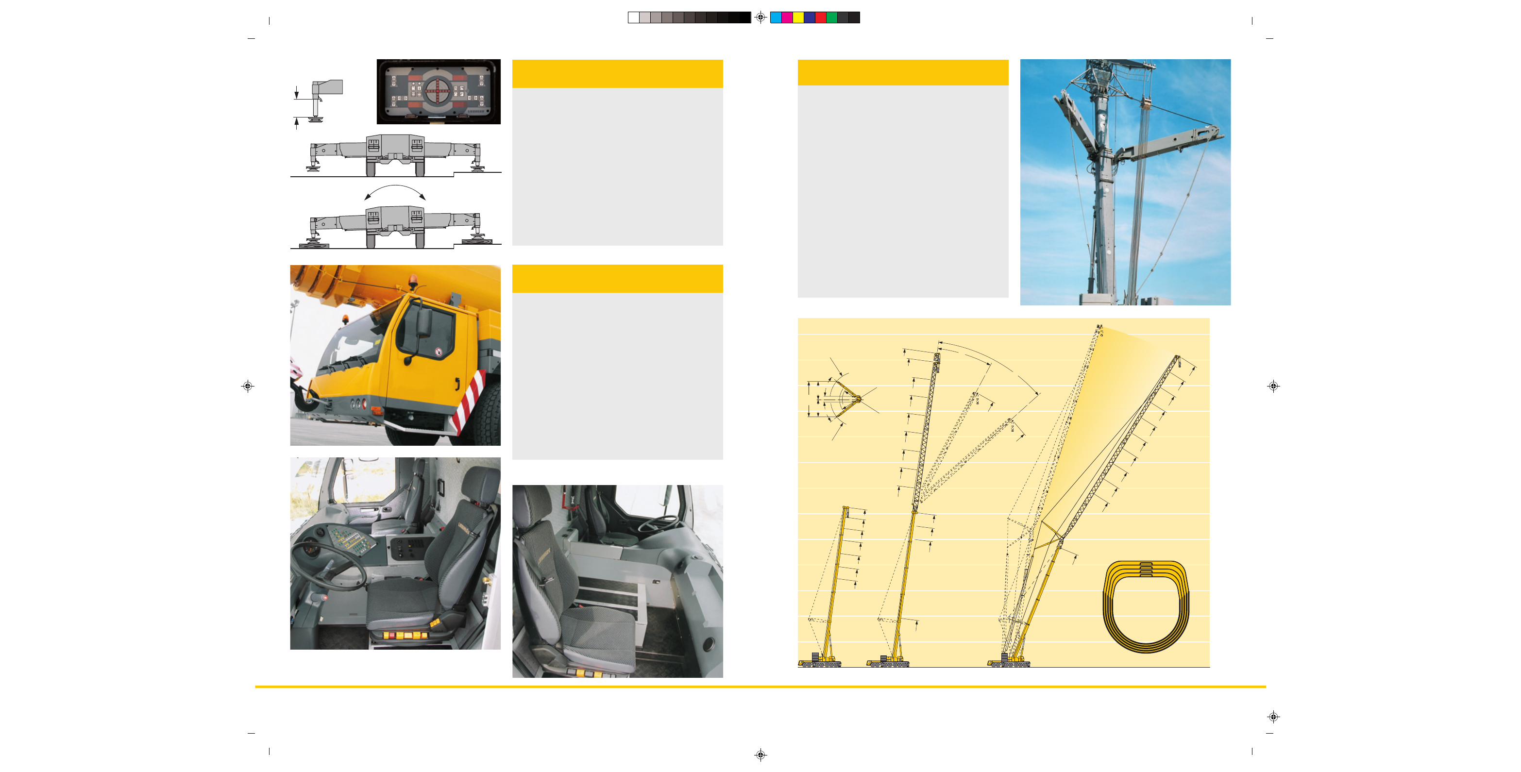
• Telescopic boom T, 15.4 m – 60 m
• Telescopic boom guying system TY, 5.25 m wide "spacer"
for TYSF and TYSN mode
• Fixed lattice jib TF (TYSF), 7 m - 56 m, mountable at 0°, 20°
or 40° on the 15.4 m – 60 m long telescopic boom
• Lattice luffing jib TN (TYSN), 14 m – 84 m, mountable on the
15.4 m – 56.4 m long telescopic boom
• Continuous load capacity interpolation during luffing of the
boom configuration TN (TYSN) between 82° and 68° telescopic
boom inclination
• Intermediate sections TF and TN equipment are identical,
intermediate sections can be slid into one another for
transportation
• Jib A-frames with T-adapter and N-base section form a
complete mounting/transport unit and can be fitted with just
4 pins
• Easy-to-rig stay rods which remain on the intermediate
sections during transportation
• Auxiliary winch on the counterweight frame for easy reeving
of the hoist and luffing ropes
• Rigging of the jib can be performed in suspended condition
on restricted sites
• Winch 2 for 2-hook operation on the lattice jib
• Winch 3 for jib variation. The variation winch forms one unit
with the variation block. The variation rope remains reeved
during transportation.
Multi variable boom configuration
system
• Supporting basis: 10 m x 9.5 m or 10 m x 6.23 m
• Fixed suporting pads with lateral compensation
• Supporting rams with 600 mm travel
• Level control of the outriggers, all-automatic levelling of the
crane during the supporting procedure by "push-button
control"
• 2 x 9° lateral inclination of the carrier, thus simple underlay
of the supporting pads
• Inclinometer (electronic inclination indication), two displays
on the carrier and a display on the LICCON monitor in the
crane cab
• 2 supporting force indicators on the control panels on the
carrier and on the LICCON display screen to indicate the
supporting force on the supporting rams
• 4 projectors for the illumination of the supporting zone
• Axle locking (blocking of the suspension for the displacement
with equipment) controllable from the driver’s cab
• Operation of the outrigger system in accordance with the
rules for the prevention of accidents
Setting crane on outriggers –
quick, convenient and safe
oviform boom profile
60 m
56.5 m
51.4 m
46.3 m
41.1 m
36 m
30.8 m
56.6 m
51.4 m
46.3 m
15.4 m
F 49 m
F 42 m
F 35 m
F 28 m
F 21 m
F 14 m
F 7 m
F 49 m
F 49 m
N 84 m
N 77 m
N 70 m
N 63 m
N 56 m
N 49 m
N 42 m
N 35 m
N 28 m
N 21 m
46.3 m
T 60 m
F 56,6 m
T 56.6 m
F 56 m
20°
40°
82°
68°
6.4
6.2
12.6
R = 10
R = 6.6
R = 5.6
R = 9.8