Briggs & Stratton 01929-1 User Manual
Page 9
9
Briggs & Stratton Power Products Automatic Transfer Switch
Installation and Operator’s Manual
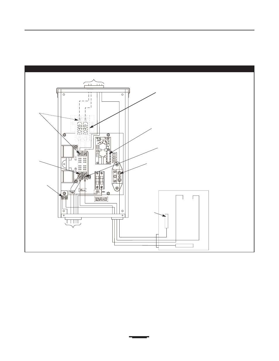
Figure 4 — A Typical Installation Diagram for Transfer Switch
Main
Main Distribution Panel
Ground Bus
Neutral
Bus
To Generator
Neutral
Terminal
To Utility Power
Supervisory
Contacts
Load
Connection
Ground Lug
Generator
Connection
Utility
Connection
NOTE: Models 01928-1 and 01929-1 have a utility disconnect
circuit breaker built into the transfer switch enclosure.