Hardware installation, Se ct io n – Belkin F1DP101M User Manual
Page 15
12
1
2
3
4
5
6
7
8
9
se
ct
io
n
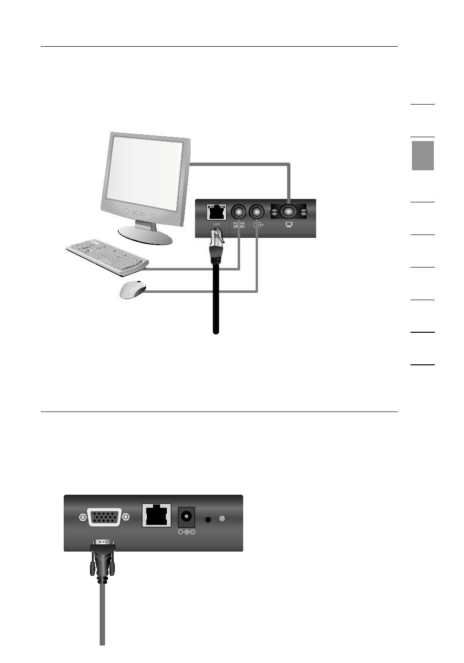
Hardware Installation
2.3 Locate and connect a cable from your local area network to the
RJ45 Ethernet port on the back of the IP Device. (Refer to
diagram below.)
���
Step 3 Connecting the KVM Switch or Server
to the IP Device
3.1 Make sure your KVM switch and all connected servers are powered off.
3.2 Using the included KVM cable kit, connect the single DB15 connector
to the “KVM In” port on the back of the IP Device. (Refer to
diagram below.)
������
������
�������
��������
�����
�
See also other documents in the category Belkin Hardware:
- Wireless G Plus MIMO Router F5D9230-4 (120 pages)
- F5U237EA (12 pages)
- F5D7330 (2 pages)
- F5D7230AU4P (136 pages)
- BASIC F7D1101AK (39 pages)
- F5D7632EA4A (504 pages)
- F5D7231-4P (146 pages)
- F5U103 (11 pages)
- VISION N1 (4 pages)
- F5D5630AU (28 pages)
- Wireless USB Hub F5U303 (28 pages)
- PM01110-A (105 pages)
- F5D9050UK (251 pages)
- USP Plus Hub F5U307 (12 pages)
- F5D9230UK4 (667 pages)
- F5U503 (112 pages)
- F5D6051 (42 pages)
- F5U210 (20 pages)
- F5D7000AU (2 pages)
- F5D5000t (53 pages)
- F5U122-PC (17 pages)
- F5D8235-4 (89 pages)
- F7D3402AU (36 pages)
- F1DC101C-US (10 pages)
- BUS STATION F5U100-ORG (12 pages)
- F1PI242EGAU (4 pages)
- USB 2.0 Notebook Card F4U008 (7 pages)
- PM01111 (2 pages)
- SC to SC Duplex patch cord A2F40277 (1 page)
- N600 DB (59 pages)
- F5D7130 (36 pages)
- ADSL2+ Modem with Wireless G Router F5D7632uk4A (86 pages)
- F5D7234-4 (105 pages)
- F5D4070 (21 pages)
- POWERLINE NETWORKING ADAPTERS PM01141ea (18 pages)
- USB 2.0 5-Port PCI Express Card F5U252ea (72 pages)
- F5U219 (17 pages)
- 7 22868 53439 7 (1 page)
- F4D116 (1 page)
- Wireless Router F5D7234-4-H (106 pages)
- P74065 (13 pages)
- F5U217 (64 pages)
- PLAY MAX 8820ED00378_F7D4301_V1 (40 pages)
- IEEE 1394 PCMCIA Cardbus F4U011 (7 pages)
- PM00760-A F4U001 (19 pages)