Service (cont.), Fig. 43 tank heater switch terminals – Bunn FMD-1 FMD-2 User Manual
Page 39
39
12
11
9
8
7
J4
J1
J2
J3
J1
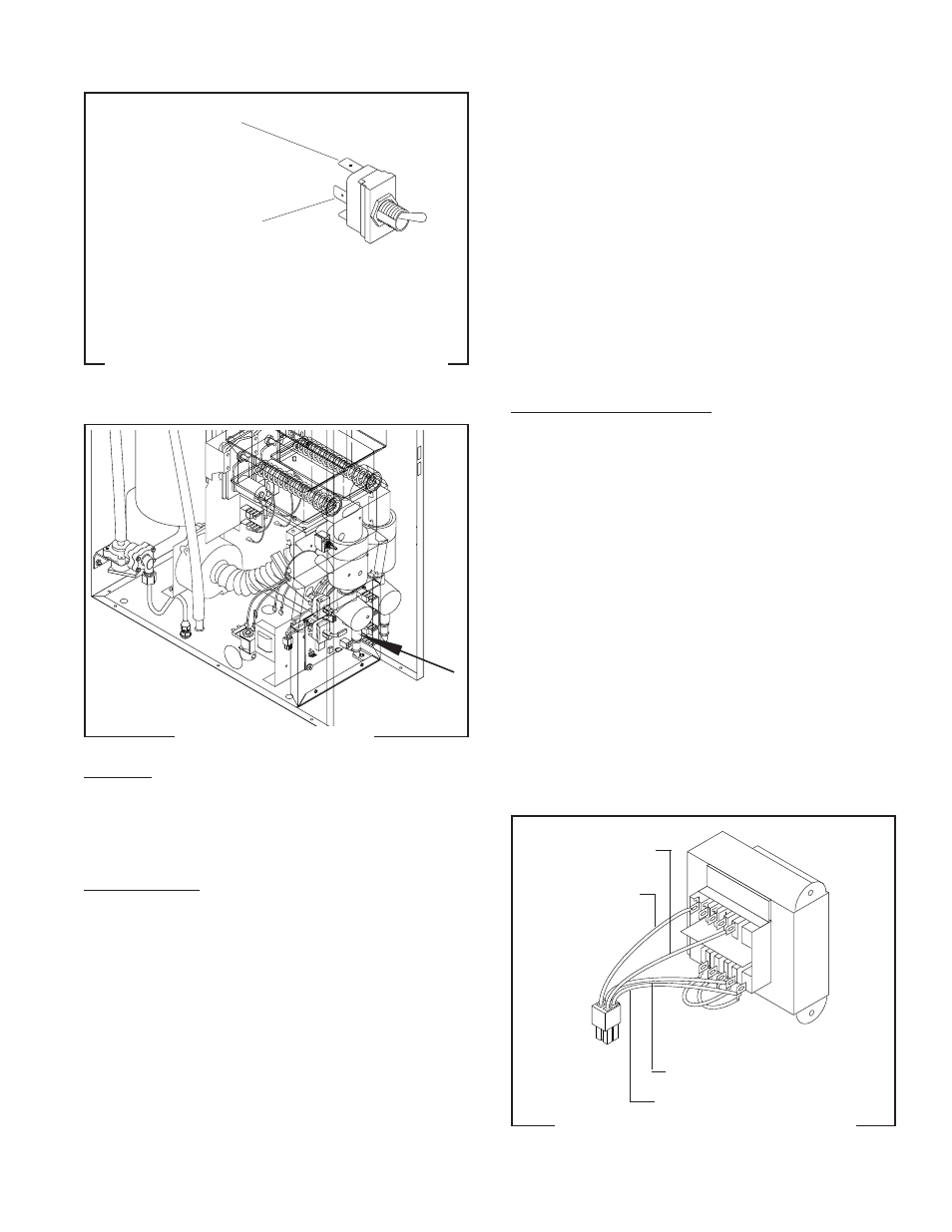
SERVICE (cont.)
FIG. 43 TANK HEATER SWITCH TERMINALS
P1219
BLK to Main
Harnesss
BLK from Main
Harness
TRANSFORMER - FMD-2 ONLY
FIG. 44 TRANSFORMER
P1666
Location:
The transformer is located behind the lower
front access cover, mounted on the right rear side
of the component bracket.
Test Procedure:
1. Disconnect the dispenser from the power source.
2. Disconnect the four pin plug from the main har-
ness from the four pin connector on the trans-
former.
3
Check the voltage across black wire pin 1 and the
white wire pin 2 on the plug from the main harness.
Connect the dispenser to power source. The indi-
cation must be:
a. 120 volts ac for two wire 120 volt models.
b. 120 volts for three wire 120/208 volt models and
three wire 120/240 volt models.
4. Disconnect the dispenser from the power source.
If voltage is present as described reconnect the plug
and the connector and proceed to #5.
If voltage is not present as described, refer to the
wiring diagrams and check the main wiring harness.
5. Check the voltage between J1-1 and J1-2 on the
eight pin connector at the control board. Connect
the dispenser to the power source. The indication
must be 24 volts ac.
If voltage is present as described the transformer is
operating properly.
If voltage is not present as described, replace the
transformer.
Removal and Replacement:
1. Loosen the two #8-32 screws securing the com-
ponent bracket to the dispenser housing base.
2. Pull component bracket out the front of the dis-
penser far enough so the transformer connector
can be disconnected from the main wiring har-
ness.
3
Disconnect the transformer four pin connector
from the four pin plug on the main wiring harness.
4. Remove the two #6-32 keps nuts securing the
transformer to the rear of the component bracket.
5. Remove and discard the transformer.
6. Install new transformer on the rear of the compo-
nent bracket and secure with two #6-32 keps nuts.
7. Connect the four pin connector on the transformer
to four pin plug on the main wiring harness.
8. Place the component bracket into position and
tighten the two #8-32 screws.
12
11
9
8
7
WHI/BLK - T12
WHI/GRN - T7
WHI - 120V T2, 240V T6
BLK - TI
FIG. 45 TRANSFORMER TERMINALS
P1703
29112 101598