Service (cont.), J1 j4 fig. 13 control board connectors, Control board - fmd-2 only (cont.) j2 j3 – Bunn FMD-1 FMD-2 User Manual
Page 22
22
RELE
ASE BUTTON W
HEN CUP IS 2/3 FULL
PLACE
CUP HERE
PUSH and H
OLD BUTTO
N U
NTIL CUP
IS 2/3 FULL, THEN RELEASE
RELEASE BUTTON WHEN CUP IS 2/3 FULL
PLACE
CUP HERE
PLACE
CUP HERE
PUSH and HOLD BUTTON UNTIL CUP
IS 2/3 FULL, THEN RELEASE
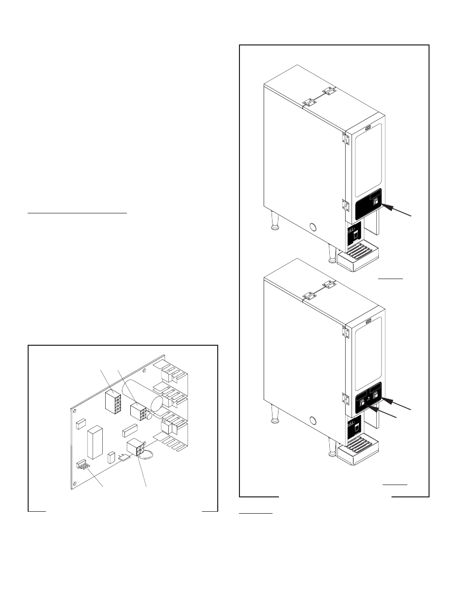
DISPENSE SWITCH(S) - FMD-1 & FMD-2
FIG.14 DISPENSE SWITCH
P1614
Location:
The dispense switch(es) is (are) located on
the lower outside of the dispenser door.
FMD-1
FMD-2
SERVICE (cont.)
7. Check the voltage across the red (+) terminal and
the black (-) terminal of the auger motor with a
voltmeter. Connect the dispenser to the power
source. Press and hold the appropriate dispense
switch. After a delay of about .6 seconds, the
indication must be between +4.0 and +24.5 volts
dc.
If the voltage is present as described, the hopper
motor control circuitry is operating properly.
If the voltage is not present as described, replace the
control circuit board.
Removal and Replacement:
1. Disconnect the three plugs on the main wiring
harness from the connectors on the control board.
2. Remove the four #6-32 keps nuts securing the
control board to the component bracket.
3. Remove control board and discard.
4. Install new control board on the component bracket
using four #6-32 keps nuts.
5. Reconnect the three plugs on the main harness to
the connectors on the control board.
J4
J2
J3
J1
J1 J4
FIG. 13 CONTROL BOARD CONNECTORS
P1640
CONTROL BOARD - FMD-2 ONLY (CONT.)
J2 J3
29112 101598