Service (cont.), Hopper drive board - fmd-1 only (cont.) – Bunn FMD-1 FMD-2 User Manual
Page 28
28
12
11
9
8
7
J4
J1
J2
J3
J1
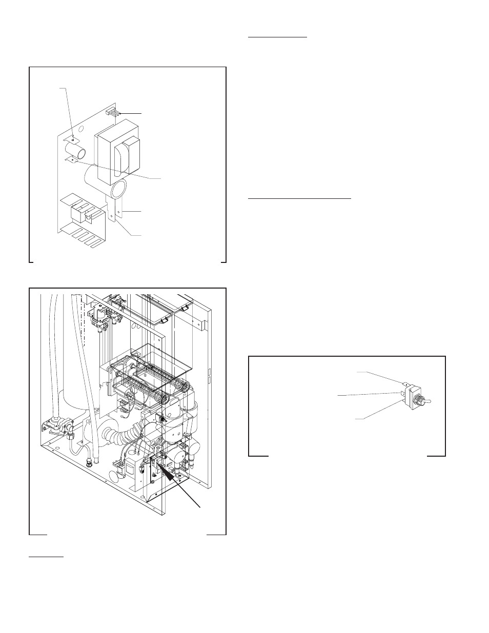
HOPPER DRIVE BOARD - FMD-1 ONLY (cont.)
SERVICE (cont.)
J1
J1 Connector for
Three Pin Plug from
Potentiometer
RED from Hopper
Motor
FIG. 22 HOPPER DRIVE BOARD TERMINALS
P1669
BLK from
Hopper Motor
RED/WHI from
Main Harness
WHI from Main
Harness
INCREASE/DECREASE SWITCH - FMD-2 ONLY
FIG. 23 INCREASE/DECREASE SWITCH
P1666
Location:
The increase/decrease switch is located on the
lower left front of the whipper motor mounting panel.
Test Procedure:
1. Disconnect the dispenser from the power source.
2. Disconnect the wires from the switch terminals.
3. Check for continuity between the center terminal
and upper terminal with switch in the decrease
position (lower). Check for continuity between the
center terminal and the lower terminal with the
switch in the increase position (upper).
If continuity is present as described, the switch is
operating properly.
If continuity is not present as described, replace the
switch.
Removal and Replacement:
1. Open the dispenser door.
2. Remove the facenut securing the increase/de-
crease switch to the whipper motor mounting
panel.
3. Remove switch with wires attached from the back
side of the whipper motor mounting panel.
4. Disconnect the wires from the switch and discard
the switch.
5. Refer to Fig. 24 when connecting the wires to the
new switch.
6. Install new switch with wires attached through the
hole in the whipper mounting panel and secure
with facenut.
RED/BLK from Control
Board J2-6
GRN from Control
Board J2-9
BRN/BLK from Control
Board J2-1
FIG. 24 INCREASE/DECREASE SWITCH
TERMINALS
P1208
29112 101598