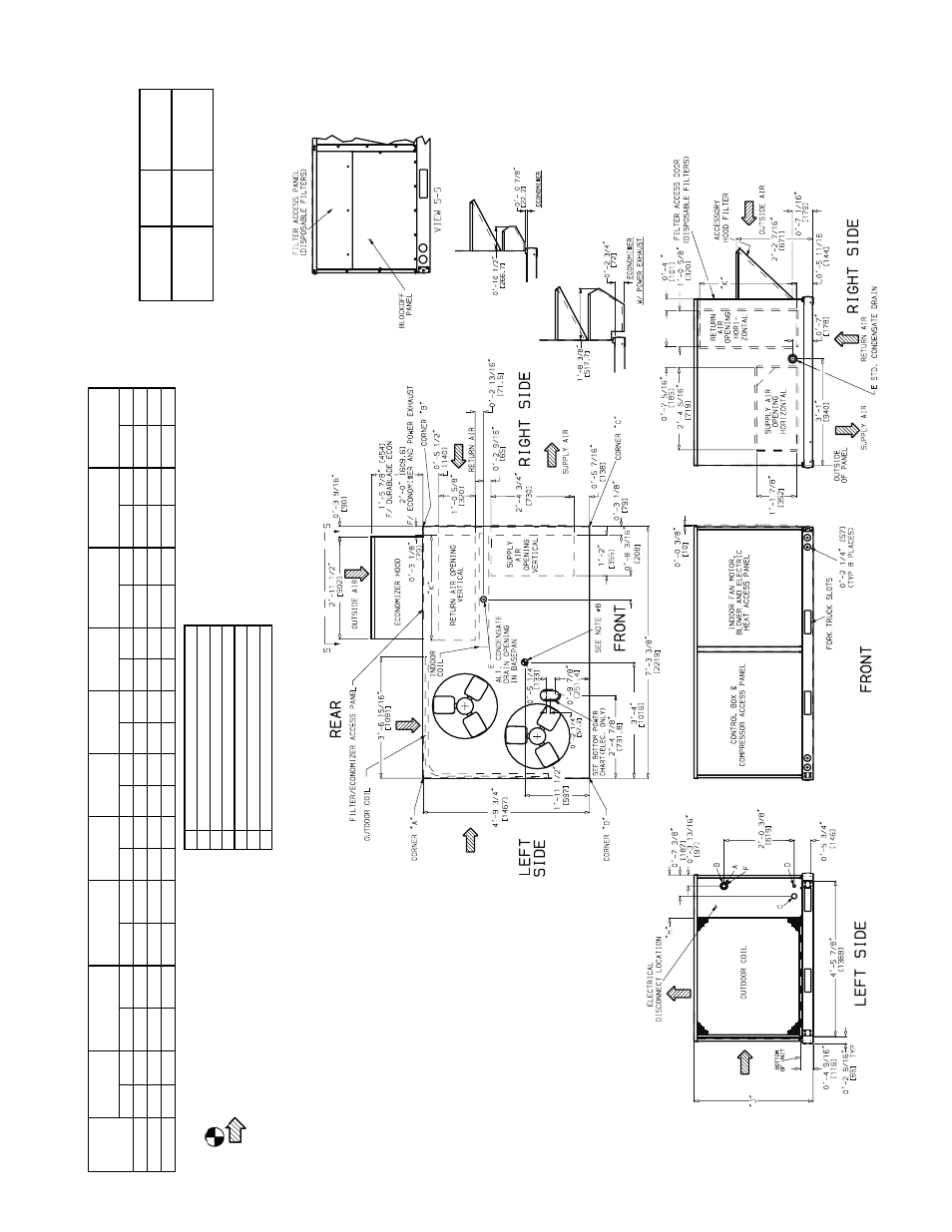
Fig. 6 — bas e uni t dime nsi ons – Bryant 548D User Manual
Page 5
—
5
—
UNIT
548D
S
T
D UNIT
W
E
IGHT
DUR
ABL
ADE
E
C
ON
OM
IZ
E
R
W
E
IGHT
E
C
ONOM
I$E
R
W
E
IGHT
CORNE
R
W
E
IGHT
(A
)
CORNER
W
E
IGHT
(B
)
CORNER
W
E
IGHT
(C
)
CO
R
N
E
R
W
E
IGHT
(D
)
“H”
“
J”
“K”
Lb
K
g
L
b
K
g
Lb
K
g
Lb
K
g
L
b
K
g
Lb
K
g
L
b
K
g
Ft
-i
n.
m
m
Ft
-i
n.
m
m
Ft
-i
n
.
m
m
090
940
426
44
20
62
28
207
94
1
7
8
8
1
254
115
301
1
3
6
2
-
0
7
/
8
63
2
3
-5
5
/
16
10
50
2
-9
11
/
16
85
6
102
965
438
44
20
62
28
212
96
1
8
3
8
3
261
119
309
1
4
0
2
-
0
7
/
8
63
2
3
-5
5
/
16
10
50
2
-9
11
/
16
85
6
120
1015
460
44
20
62
28
223
101
1
9
3
8
8
274
124
325
1
4
7
2
-1
0
7
/
8
88
5
4
-1
5
/
16
12
53
3
-0
3
/
8
92
4
NO
T
E
S:
1
.
Dim
e
n
s
io
n
s
in
[ ]
a
re
i
n
m
illim
e
te
rs
.
2
.
C
e
nter
of g
ra
v
it
y.
3
.
D
ir
ecti
on o
f ai
rfl
o
w
.
4
.
Ductwo
rk
to
be a
ttached
to acce
ssor
y
roof
curb o
n
ly
.
5
.
Mi
ni
m
u
m
cl
ear
an
ce (l
oca
l
codes o
r j
u
ri
sdi
c
ti
on m
a
y pre
vai
l)
:
a.
B
o
ttom to comb
u
s
ti
b
le surf
aces (w
he
n
no
t
usi
n
g
cur
b
) 0
in
ch
es
,
on h
o
ri
z
ont
al
di
schar
ge u
n
it
s w
it
h e
lectr
ic
heat 1
i
n
. cl
ea
rance t
o
ductw
ork f
o
r 1 f
t.
b
.
C
onden
ser coi
l,
f
o
r pro
per ai
rf
lo
w
, 36
i
n
. one si
d
e
, 12 i
n
. th
e
other
. Th
e si
de g
e
tti
ng t
he g
re
a
ter
cl
e
a
rance
is
opti
ona
l.
c.
Ov
e
rhea
d, 60 i
n
. to assu
re p
rope
r cond
enser
f
an op
er
ati
on.
d.
B
e
tw
ee
n un
it
s,
contr
o
l bo
x si
d
e
, 42
in
. per
N
E
C
(N
ati
o
nal
E
lectr
i-
ca
l Co
d
e
).
e
.
B
e
tw
ee
n un
it
and
ung
rounde
d sur
faces
, co
ntrol
bo
x si
de
,
36
in
.
per
N
E
C
.
f.
B
e
tw
ee
n uni
t an
d b
loc
k or
concr
e
te w
a
lls
and ot
her g
ro
unde
d
surf
ace
s
, contr
o
l bo
x si
de
,
42 i
n
. p
e
r N
E
C
.
g.
H
o
ri
z
o
n
tal
supp
ly
and r
e
tur
n
e
nd, 0
i
n
ches
.
6
.
W
it
h
the
e
xcepti
o
n
of th
e cl
ear
an
ce f
o
r
the co
ndense
r coi
l a
s
state
d
in
N
o
tes
5a, b
, and
c
, a re
mo
va
b
le f
e
n
c
e or
bar
ri
cade
requ
ir
es n
o
cl
ear
ance
.
7
.
U
n
it
s ma
y be
i
n
stal
led on
comb
usti
b
le fl
oo
rs ma
de fro
m
w
ood or
C
la
ss A
, B
, or C
roof
co
v
e
ri
ng m
a
teri
al
.
8.
T
h
e ve
rt
ic
al
c
e
n
te
r
of
gr
a
v
it
y
i
s
1
′-7
1
/
2
″ [495
] f
o
r 090
and 10
2, 2
′-0
″
[610]
f
o
r 12
0 up
from
the b
o
ttom
of the
base r
a
il.
CONNECT
ION SIZ
E
S
A
1
3
/
8
″ Dia
. [3
5
] F
ie
ld
P
o
we
r S
u
p
p
ly Ho
le
B
2
1
/
2
″ D
ia
. [6
4] P
o
w
e
r S
uppl
y K
noc
k
out
C
1
3
/
4
″ D
ia
. [4
4] C
har
gi
ng P
o
rt
H
o
le
D
7
/
8
″ D
ia
. [22
] Fi
el
d
C
ontr
o
l W
iri
ng H
o
le
E
3
/
4
″ — 14
N
P
T
C
onden
sate D
rai
n
F
2″
D
ia
. [51
] P
o
w
e
r S
u
ppl
y K
noc
k
o
ut
BO
TT
O
M
PO
WER CHAR
T
, T
H
ESE HO
L
ES REQ
’D
FO
R U
S
E WI
T
H
A
CCESSO
R
Y
P
A
CKA
G
ES —
CRBT
M
PWR0
0
1
A0
0
(
1
/
2
″,
3
/
4
″) O
R
C
R
B
TM
P
W
R
002
A
00 (
1
/
2
″, 1
1
/
4
″)
*S
el
ect
ei
ther
3
/
4
″ or
1
1
/
4
″ f
o
r po
w
e
r,
de
pend
in
g on w
ir
e
siz
e
.
T
HREA
D
ED
C
O
ND
UIT
SI
ZE
WI
RE
USE
R
E
Q’D HOL
E
SI
ZE
S
(M
ax.
)
1
/
2
″″″″
24
V
7
/
8
″ [22
.2]
3
/
4
″″″″
Po
w
e
r*
1
1
/
8
″ [28
.4]
1
1
/
4
″″″″ FPT
Po
w
e
r*
1
3
/
4
″ [44
.4]
F
ig. 6
— Bas
e
Uni
t Dime
nsi
ons