MTD 190-758 User Manual
Page 6
6
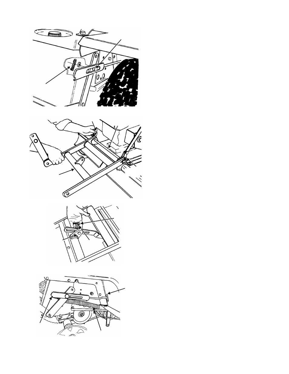
Figure 9
Figure 10
Figure 11
Figure 12
9.
Lift hitch bar assembly up and place sleeve (B)
over weld stud on hitch bar. Next, place link rod
over sleeve and secure with one flat washer (J)
and hairpin clip (E). See Figure 9.
10. Back the tractor up to the tiller and hook the
hitch bar assembly to it. See Figure 10.
NOTE:
Figure 10 is shown without the tractor for
clarity.
11. Remove one hairpin clip from hitch rod on tiller,
line up hitch bar assembly and install hitch rod.
Secure with hairpin clip. See Figure 10.
12. Secure the stabilizer link to the hitch bar
assembly with clevis pin (I), flat washer (A) and
hairpin clip (E), as shown in Figure 11.
13. Using a piece of wire, hook one end of
extension spring in the hole on the running
board and the other end of spring to the notch
in the linkage rod. See Figure 12. (On units with
a one piece fender, remove one bolt which
secures the bracket to the running board,
closest to the frame, in order to attach the
spring.)
NOTE:
Figure 12 is shown with the rear wheel
removed for clarity. It is not necessary to remove for
assembly.
Flat Washer (J)
Hairpin Clip (E)
Weld Pin
Hairpin
Clip
Hairpin
Clip
Hitch Rod
on Tractor
Hitch Bar
Assembly
Clevis Pin
(I)
Flat
Washer
(A)
Hairpin
Clip (E)
Hole in
Running
Board
Extension Spring
Notch in
Linkage Arm