Bryant Two-Speed Puron Plus Air Conditioning Unit 598B User Manual
Page 11
X.
START-UP
CAUTION:
To prevent compressor damage or personal
injury, observe the following:
• Do not overcharge system with refrigerant.
• Do not operate unit in a vacuum or at negative pressure.
• Do not disable low-pressure switch.
CAUTION:
To prevent personal injury wear safety
glasses, protective clothing, and gloves when handling
refrigerant and observe the following:
• Back seating service valves are not equipped with
Schrader valves. Fully back seat (counter clockwise)
valve stem before removing gage port cap.
CAUTION:
Do not vent refrigerant to atmosphere. Re-
cover during system repair or final unit disposal.
Follow these steps to properly start up the system:
1. The outdoor unit is equipped with a crankcase heater which
operates when the compressor is off. Energize crankcase
heater 24 hr. before starting unit. To energize heater only,
set indoor thermostat to OFF position and close power
disconnect to unit.
NOTE:
Starting the compressor without a minimum of 12 hours
of crankcase heat prior to initial start-up may result in compressor
chattering noise and possible damage to the compressor.
2. Fully back seat (open) liquid and vapor tube service valves.
3. Unit is shipped with valve stem(s) front seated and caps
installed. Replace stem caps after system is opened to
refrigerant flow (back seated). Replace caps finger tight and
tighten additional 1/12 turn (20 ft-lb torque) with wrench.
4. Close electrical disconnects to energize system.
5. Set room thermostat at desired temperature. Be sure set
point is below indoor ambient and is set low enough to
energize desired speed.
NOTE:
Bryant electronic thermostats are equipped with a 15
minute staging timer. This timer prevents the two-speed system
from operating at high speed until unit has been operating in low
speed for 15 minutes unless there is at least a 5°F difference
between room temperature and thermostat set point. To force high
speed (after a minimum of 2 minutes in low speed), adjust the set
point at least 5° below room ambient.
6. Set room thermostat to COOL and fan control to AUTO or
ON as desired. Wait for appropriate time delay(s) and 2
minute minimum low-speed run time. Operate unit for 15
minutes. Check refrigerant charge.
NOTE:
If unit has not operated within the past 12 hours or
following a unit power-up, upon the next thermostat high- or
low-speed demand, unit operates for a minimum of 5 minutes in
high speed.
XI.
CHECK CHARGE
WARNING:
Service valve gage ports are not equipped
with Schrader valves. To prevent personal injury, make
sure gage manifold is connected to the valve gage ports
before moving valves off fully back seated position. Wear
safety glasses and gloves when handling refrigerant.
A.
COOLING ONLY PROCEDURE
1. Operate unit a minimum of 15 minutes before checking
charge.
2. Measure liquid service valve pressure by attaching an
accurate gage to service port.
3. Measure liquid line temperature by attaching an accurate
thermistor type or electronic thermometer to liquid line near
outdoor coil.
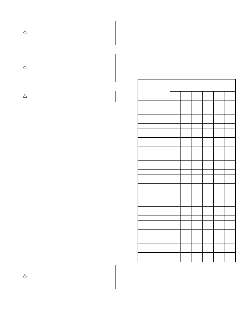
4. Refer to Table 4 for required subcooling temperature.
5. Refer to Table 3. Find the point where required subcooling
temperature intersects measured liquid service valve pres-
sure.
6. To obtain required subcooling temperature at a specific
liquid line pressure, add refrigerant if liquid line tempera-
ture is higher than indicated or reclaim refrigerant if
temperature is lower. Allow a tolerance of ± 3°F.
B.
UNIT CHARGE
Factory charge and charging method are shown on pink charging
label. Puron® refrigerant cylinders contain a dip tube which
allows liquid refrigerant to flow from cylinder in upright
position. Charge Puron units with cylinder in upright position and
a commercial type metering device in manifold hose. Charge
refrigerant into suction line.
NOTE:
Unit is to be charged in high capacity only. Charging in
low capacity may cause compressor chattering and possible
damage to the compressor.
TABLE 3—REQUIRED LIQUID-LINE TEMPERATURE (°F)
LIQUID
PRESSURE AT
SERVICE VALVE
(PSIG)
REQUIRED SUBCOOLING
TEMPERATURE
(°F)
8
10
12
14
16
18
189
58
56
54
52
50
48
195
60
58
56
54
52
50
202
62
60
58
56
54
52
208
64
62
60
58
56
54
215
66
64
62
60
58
56
222
68
66
64
62
60
58
229
70
68
66
64
62
60
236
72
70
68
66
64
62
243
74
72
70
68
66
64
251
76
74
72
70
68
66
259
78
76
74
72
70
68
266
80
78
76
74
72
70
274
82
80
78
76
74
72
283
84
82
80
78
76
74
291
86
84
82
80
78
76
299
88
86
84
82
80
78
308
90
88
86
84
82
80
317
92
90
88
86
84
82
326
94
92
90
88
86
84
335
96
94
92
90
88
86
345
98
96
94
92
90
88
354
100
98
96
94
92
90
364
102
100
98
96
94
92
374
104
102
100
98
96
94
384
106
104
102
100
98
96
395
108
106
104
102
100
98
406
110
108
106
104
102
100
416
112
110
108
106
104
102
427
114
112
110
108
106
104
439
116
114
112
110
108
106
450
118
116
114
112
110
108
462
120
118
116
114
112
110
474
122
120
118
116
114
112
486
124
122
120
118
116
114
499
126
124
122
120
118
116
511
128
126
124
122
120
118
—11—