Warning, Assembly instructions, Bl26c0 only – MTD BL26C0 User Manual
Page 8
8
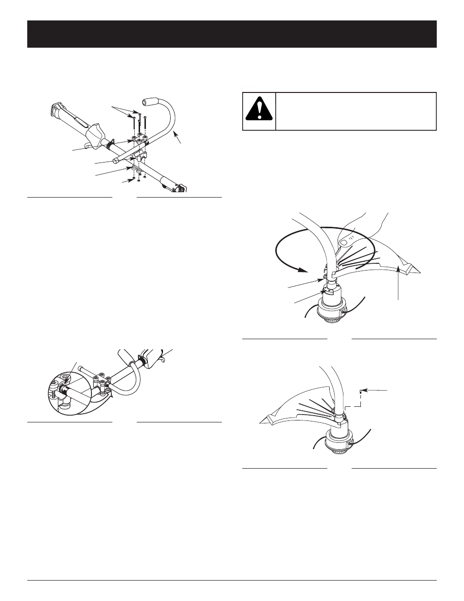
ASSEMBLY INSTRUCTIONS
INSTALL AND ADJUST THE J-HANDLE
1. Place the J-handle between the top and middle
clamp pieces (Fig. 1).
3. Place the clamps and the J-handle over the shaft
housing and onto the bottom clamp.
4. Hold each hex nut in the bottom clamp recess with a
finger. Start screws with a large Phillips screwdriver.
Do not tighten until you make the handle adjustment.
5. Slide the J-handle in or out until the arrow/white line on
the decal touches the clamp assembly (Fig. 2). You must
first loosen the screws if the handle is pre-installed.
Fig. 2
6. While holding the unit in the operating position
(Fig. 26), position the J-handle to the location that
provides you the best grip.
7. Tighten the clamp screws evenly, until the J-handle
Decal
(4) Screws
Top Clamp
J-Handle
Middle Clamp
Bottom Clamp
Nuts
Fig. 1
BL26C0 ONLY:
INSTALL THE CUTTING SHIELD
Use the following instructions if the cutting attachment
shield on your unit is not installed.
Never operate the
trimmer without the
cutting attachment shield in place to
prevent serious personal injury.
WARNING:
1. Place the cutting attachment shield onto the shaft
housing above the clamp assembly (Fig. 3).
2. Push the cutting attachment shield down to the top of
the cutting attachment assembly and then rotate the
cutting attachment shield until the screw holes align
and the guard fits into the recessed pocket (Fig. 3).
3. Install the screws with a Phillips screwdriver (Fig. 4).
Clamp
Assembly
Cutting Attachment
Shield
Recessed
Fig. 3
2. While holding the three pieces together, install the four
(4) screws through the top clamp and into middle clamp.
NOTE: The holes in the top and middle clamp will line up
only when assembled correctly.
(4) Screws
Fig. 4