Configuration, Indoor blower, Economizer standard sensors – Bryant 607C-A User Manual
Page 37
37
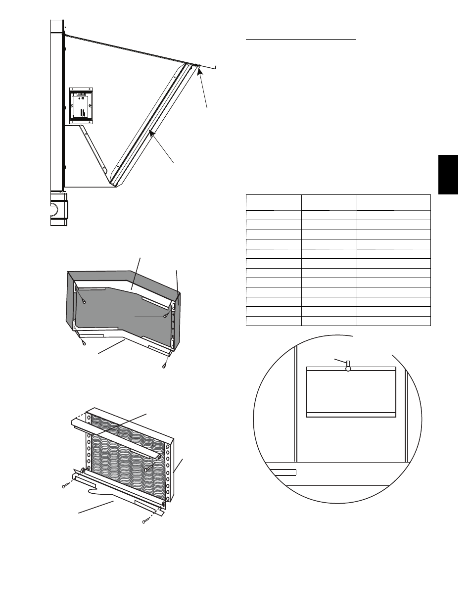
Filter
Clips
Aluminum
Filter
A09704
Fig. 36 -- Filter Installation (See through view)
Bottom
filter rack
Screw
(Note 4 and 5)
RIGHT SIDE
Evaporator
Coil
Top filter
rack
BENT COIL
Bottom
filter rack
Top filter
rack
Evaporator
Coil
STRAIGHT COIL
A09714
Fig. 37 -- Indoor Coil with Filter Rack
CONFIGURATION
Economizer Standard Sensors
OUTDOOR AIR TEMPERATURE (OAT) SENSOR— The
outdoor air temperature sensor (HH57AC080) is a 10 to 20mA
device used to measure the outdoor--air temperature. The outdoor--air
temperature is used to determine when the Economizer can be used
for free cooling. The operating range of temperature measurement is
40 to 100_F (4.4 to 37.8_C). The sensor has 8 selectable temperature
changeover setpoints. The temperature changeover is set using 3 dip
switches on the sensor. The ABCD potentiometer on the controller
should be set to the “D” position. See Fig. 40.
SUPPLY AIR TEMPERATURE (SAT) SENSOR—The supply
air temperature sensor is a 3 KΩ thermistor located at the inlet of the
indoor fan. See Fig. 38. The operating range of temperature
measurement is 0_ to 158_F (--17.8_ to 70_C). See Table 15 for
sensor temperature/resistance values. The temperature sensor looks
like an eyelet terminal with wires running to it. The sensor is located
in the “crimp end” and is sealed from moisture.
Table 15 – Supply Air Sensor Temperature/Resistance Values
TEMPERATURE
(_F)
CELSIUS (_C)
RESISTANCE (OHMS)
---22
---30
53,010
---4
---20
29,091
14
---10
16,590
32
0
9,795
50
10
5,970
68
20
3,747
77
25
3,000
86
30
2,416
104
40
1,597
122
50
1,080
140
60
746
158
70
525
Indoor
Blower
Supply Air Temperature
Sensor (SAT)
A09707
Fig. 38 -- SAT Location
607C
--
--
A