Warning, Accessories, Installation – Bryant 607C-A User Manual
Page 30
30
VERTICAL ECONOMIZER
(FACTORY INSTALLED OPTION)
GENERAL
Economizers are recommended for only commercial packaged
products that have X13 motors. The Economizer system utilizes
the latest technology available for integrating the use of free
cooling with mechanical cooling for rooftop units. The solid state
control system optimizes energy consumption, zone comfort, and
equipment cycling by operating the compressors when the outdoor
air temperature is too warm, integrating the compressor with
outdoor air when free cooling is available, and locking out the
compressor when outdoor air temperature is too cold. Demand
ventilation is supported.
The Economizer system utilizes gear--drive technology with a
direct--mount spring return actuator that will close upon loss of
power. The Economizer system comes standard with an outdoor air
temperature sensor, a supply air temperature sensor, and low
temperature compressor lockout switch. Indoor enthalpy, outdoor
enthalpy, and CO
2
sensors are available for field installation.
Barometric relief dampers provide natural building pressurization
control. Barometric relief dampers are built into the design and are
standard. See Table for Hood Package contents. See Table 11 for
sensor usage.
Table 10 – Package Contents
SMALL CHASSIS
(Sizes 30)
LARGE CHASSIS
(Sizes 36, 42, 48, and 60)
Qty
Content Description
Qty
Content Description
1
Hood Side, Right
1
Hood Side, Right
1
Hood Side, Left
1
Hood Side, Left
2
Angle, Filter
2
Angle, Filter
1
Aluminum Filter
(20---1/2” x 16---1/2 x 1”)
(521 x 419 x 25 mm)
1
Aluminum Filter
(20---1/2” x 16---1/2 x 1”)
(521 x 419 x 25 mm)
18
Screws
(#10 --- 14 x 5/8” w/Seal
Washer)
18
Screws
(#10 --- 14 x 5/8” w/Seal
Washer)
2
Screws
(#8 --- 18 x 3/4” Type B Pan
Head)
2
Screws
(#8 --- 18 x 3/4” Type B Pan
Head)
1
Bracket, Sensor
Table 11 – Economizer Sensor Usage
APPLICATION
ECONOMIZER WITH OUTDOOR AIR DRY BULB
SENSOR
Accessories Required
Outdoor Air Dry Bulb
None, The outdoor air dry bulb sensor is factory
installed.
Single Enthalpy
HH57AC078
Differential Enthalpy
HH57AC078 and CRENTDIF004A00*
CO
2
for DCV Control
Using a Wall---Mounted
CO
2
Sensor
33ZCSENC02 or CGCDXSEN004A00
CO
2
for DCV Control
Using a Duct---
Mounted CO
2
Sensor
33ZCSENC02 or
CGCDXSEN004A00{
and 33ZCASPCO2 or
CGCDXASP00100**
or
CRCBDIOX005A00{ {
*CRENTDIF004A00 accessory is used on many different base units. As
such, these kits may contain parts that will not be needed for installation.
{
33ZCSENCO2 and CGCDXSEN004A00 are accessory CO
2
sensors.
**33ZCASPC02 AND CGCDXASP00100 are accessory aspirator boxes
required for duct---mounted applications.
{{
CRCBDIOX005A00 is an accessory that contains both 33ZCSENCO2
AND 33ZVASPC02 accessories.
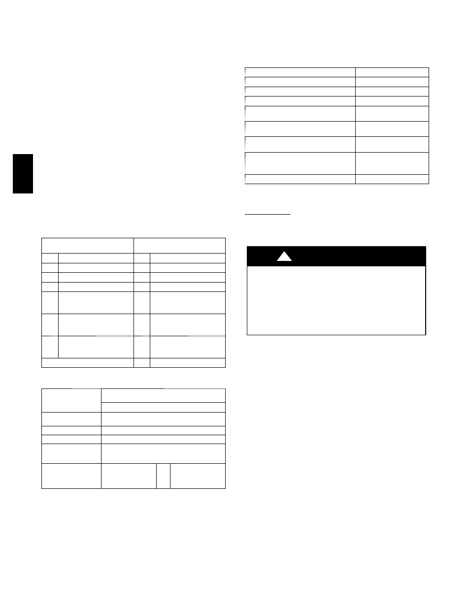
ACCESSORIES
The economizer has several field--installed accessories available to
optimize performance. Refer to Table 12 for authorized parts.
Table 12 – Accessory List
DESCRIPTION
PART NUMBER
Outdoor Air Enthalpy Sensor
HH57AC078
Indoor Air Enthalpy Sensor
CRENTDIF004A00
Return Air CO
2
Sensor (4---20 mA)
CRCBDIOX005A00
CO
2
Room Sensor (4---20 mA)
33ZCSENX02 Or
CGCDXSEN004A00
Aspirator Box for duct Mount CO
2
Sensor
(4---20 mA)
33ZCASPC02 Or
CGCDXASP001A00
Space Temperature and CO
2
Room
Sensor with Override (4---20mA)
33ZCT55C02
Space Temperature and CO
2
Room
Sensor with Override and Set Point
(4---20mA)
33ZCT56C02
Heat Pump Relay Package
CPRLYKIT001A00
INSTALLATION
Small Chassis
To install the Vertical Economizer on the small chassis perform the
following procedure:
1. Turn off unit power supply and install lockout tag.
ELECTRICAL SHOCK HAZARD
Failure to follow this warning could result in personal
injury or death.
Before installing or servicing system, always turn off main
power to system and install lockout tag. There may be more
than one disconnect switch. Turn off accessory heater
power switch if applicable.
!
WARNING
2. Remove economizer hood top panel from the return side of
the unit. See Fig. 23. Keep screws and panel next to the
unit.
3. Open economizer hood package found on the top skid.
4. Remove red shipping tape that attaches the outside air
temperature (OAT) sensor to the economizer assembly.
Using two #8 fasteners, found in the hood package, attach
the OAT sensor to the economizer according to Fig. 24.
NOTE: See label attached to economizer for OAT installing
details.
5. Remove horizontal return duct cover panel and cut the wire
ties that hold the hood divider to the economizer assembly.
Slide hood divider off from the two slots holding it in place
and place next to the unit. See Fig. 25.
607C
--
--
A