Underside, Underside -7 – Toshiba SATELLITE U500 User Manual
Page 43
User’s Manual
2-7
Satellite U500/U500D, Satellite Pro U500/U500D
Underside
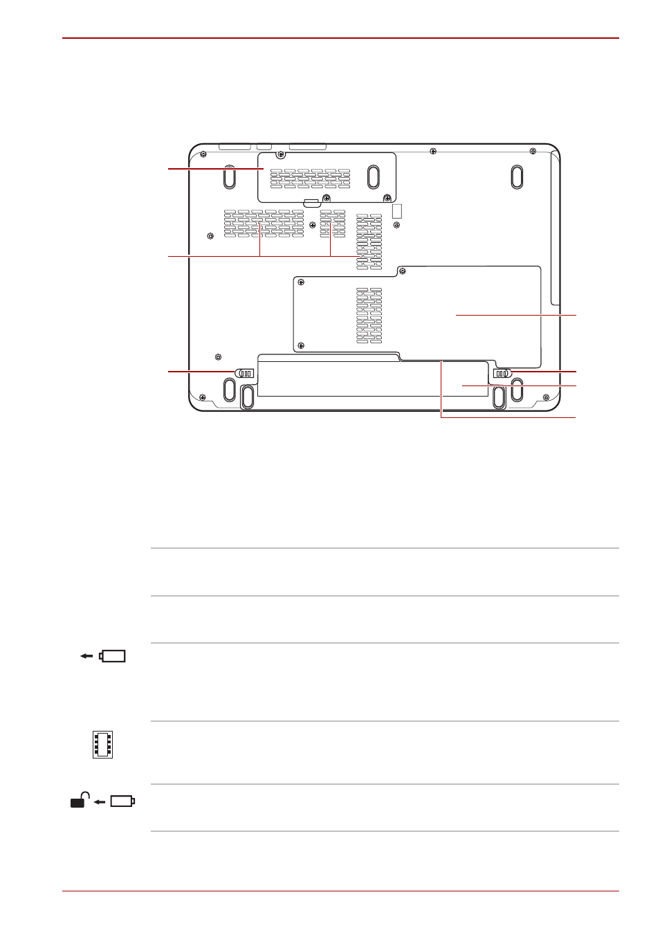
The following figure shows the underside of the computer. Make sure the
display is closed before turning over your computer.
Figure 2-4 The underside of the computer
1
5
3
4
6
7
2
1.
Wireless LAN Module cover
2.
Cooling Vents
3.
Battery Release Latch
4.
HDD/Memory Module cover
5.
Battery Pack Lock
6.
Battery Pack
7.
SIM card slot* (Under the
battery pack)
1
Wireless LAN Module Cover
This cover protects the Wireless LAN module.
2
Cooling Vents
Cooling vents help prevent the CPU from overheating.
3
Battery Release Latch
Slide and hold this latch to release the battery pack for removal. For
detailed information on removing the battery pack, refer to Chapter 6,
.
4
Hard Disk and Memory Module Cover
This cover protects the hard disk and the memory module. Refer to the
section in Chapter 8,
5
Battery Pack Lock
Slide this lock to prepare the battery pack for removal.