Essential circuit isolation – Briggs & Stratton 50A NEMA 1 User Manual
Page 6
6
Briggs & Stratton Power Products Manual Transfer Switch
Installation and Owner’s Manual
ESSENTIAL CIRCUIT
ISOLATION
Essential electrical loads are loads that will be powered by
the Standby Generator System. Essential loads are grouped
together and wired into the transfer switch.
TO THE INSTALLER: Consult with Standby
Generator System owner(s) to discuss their
“Selection of Essential Circuits”, described in
owner’s manual.
Ensure that the total of the selected load circuits fed by this
transfer switch are within the generator's rated capacity.
The following requirements apply to this type of isolation
system:
• The Manual Transfer Switch is installed after the main
distribution panel.
• The Manual Transfer Switch has a load rating of 60 Amps.
This is the maximum load rating of the essential loads.
All wiring must conform to national, state and local codes.
The illustration in Figure 2 depicts the Standby Generator
System and assumes the utility is supplying 120/240 Volt,
single-phase electrical service.
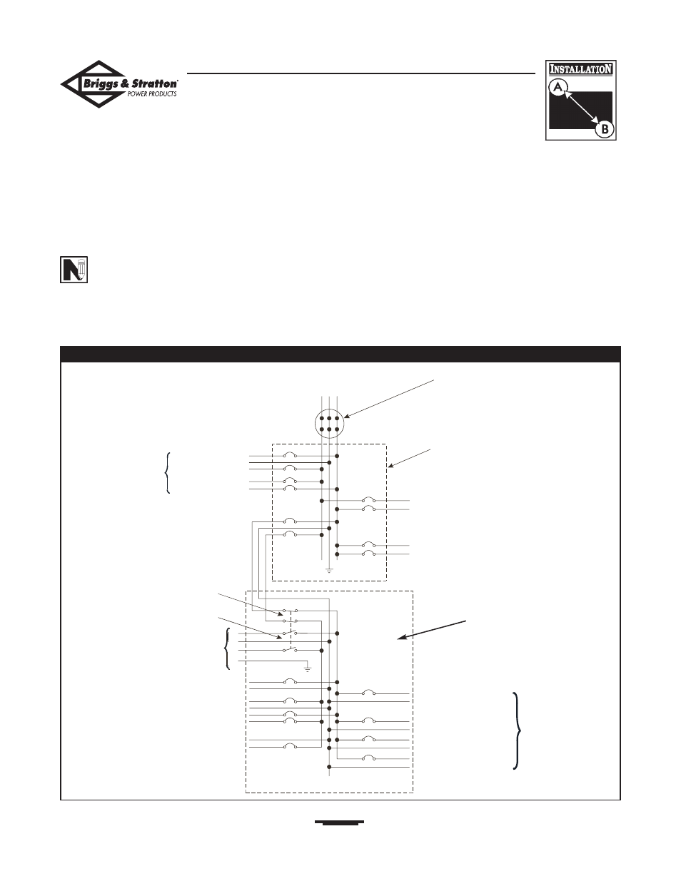
Figure 2 — Typical System Diagram with Essential Circuits
To Utility Power
Watt Meter
Main Distribution Panel
To Air Conditioner (240V)
To Other Circuits (120V)
To Range
To Water Heater
240V
To Briggs & Stratton
Standby Generator
120V To Microwave
120 V To Bathroom
240V To Well Pump
120V To Sump Pump
120V
To Furnace Blower
To Lights
To Refrigerator
120V To Freezer
Manual Transfer Switch
(in utility position)
Neutral
Utility Supply
Generator Supply