1 installing the weight kit, Warning, 2 installing the boot assembly – Bush Hog GC-250 User Manual
Page 12
SECTION III
INSTALLATION AND SETUP
3-1 Installing the Weight Kit
!
!
WARNING!
The front weight kit is designed to provide stabili-
ty of operation when the Grass Catcher is attached
to the machine.
The front weight and holder brackets must be
removed when the ZT is in use without the grass
catcher attached.
Operation of the ZT with the weight kit in place
without the grass catcher could cause loss of trac-
tion and steering control resulting in injury or
death.
NOTE: The removeable weight is heavy and care
should be taken when lifting the weight. Be sure
you have a firm grip on the weight. Position your
hands when placing the weight in the brackets so
it will not set down on your hands or fingers.
A. Begin by removing the two pan head screws that
secure the foot panel to the frame front crossmember
(Figure 2). Retain the fasteners for reinstallation. Lift
the floor panel off the frame and lay aside for reinstalla-
tion.
Figure 2
Pan Head Screws
Foot Panel
Figure 3
Figure 4
Weight
Front
Crossmember
Foot Panel
Mount
Bracket
Weight Brackets
Install the weight brackets to the front crosmember with
the weight bracket hangers passing through foot panel
mount brackets as shown in (Figure 3).
B. The front weight is 3” x 4” x 18” long and
weighs approximately 60 pounds. If you are not
capable of lifting 60 pounds with ease, get help to
perform this step.
Place the weight into the weight brackets with the 4”
side down. Make sure the weight is completely into the
brackets and not sitting on the edge of the brackets.
See (Figure 4). When the weight is securely in place
reinstall the foot panel.
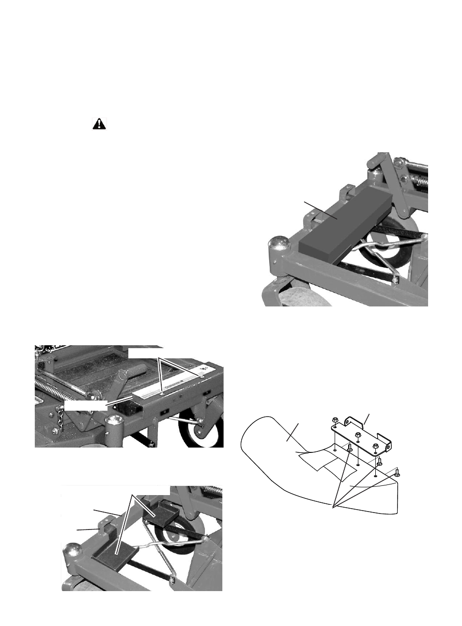
3-2 Installing the Boot Assembly
A. Assemble the Boot Plate to the Boot. Use the three
5/16” x 3/4” carriage bolts and 5/16” flange nuts sup-
plied in bag of fasteners.
Place the Boot Plate atop the Boot and align holes.
Place the carriage bolts through from the inside of the
boot with the heads down. Apply the flange nuts and
leave slightly loose. Refer to (Figure 5).
B. After the Boot is assembled it is ready to attach to
the mower deck. Place the Boot Plate between the
mounting lugs on the mower deck. Align the holes and
place the Boot Rod supplied in kit through the holes
and pin in place with the 3/32” x 2” hair pin supplied in
kit.
Figure 5
Boot Plate
5/16” x 3/4” Carriage Bolts
5/16” Flange nuts
Boot
10