Connecting the system, Connecting the power cord (1) – Pioneer AVIC-X1 User Manual
Page 10
9
Connecting the System
ENG/MASTER 96
10
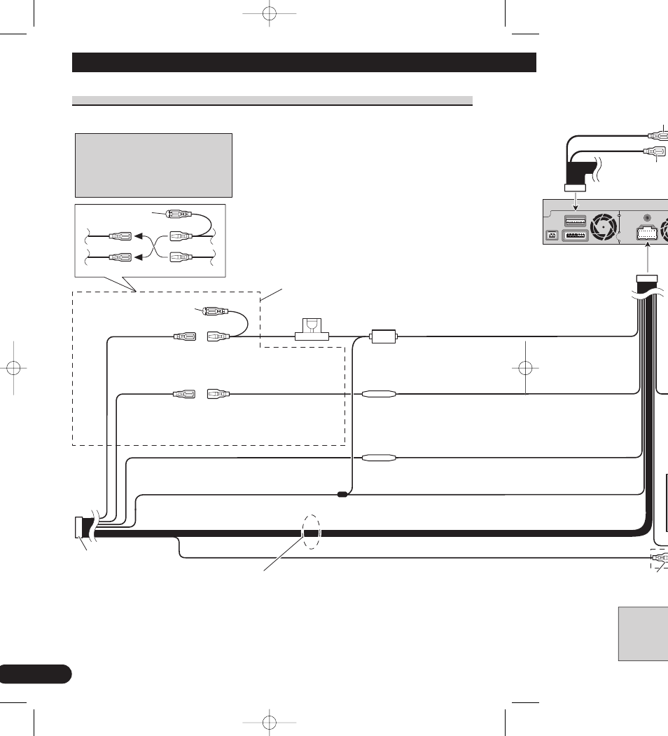
Connecting the power cord (1)
Connect leads of the same
colour to each other.
C a p ( 1 * )
When not using this terminal,
do not remove the cap.
ISO connector
Fuse holder
1*
2*
4*
3*
5*
Yellow (2*)
To terminal always supplied
with power regardless of
ignition switch position.
Red (4*)
To electric terminal controlled
by ignition switch (12 V DC)
ON/OFF.
Yellow (3*)
Back-up
(or accessory)
Red (5*)
Accessory
(or back-up)
Black (earth)
To vehicle (metal) body.
Orange/white
To lighting switch terminal.
Note:
In some vehicles, the ISO connector
may be divided into two. In this case,
be sure to connect to both connectors.
Fuse resistor
GUIDE O
SYSTEM
CONTR
Fuse resistor
Note:
Depending on the kind of vehicle, the
function of 3* and 5* may be different.
In this case, be sure to connect 2* to 5*
and 4* to 3*.
Blue (6*
Speaker leads
White:
Front left +
White/black: Front left ≠
Grey:
Front right +
Grey/black:
Front right ≠
Green:
Rear left + or Subwoofer +
Green/black: Rear left ≠ or Subwoofer ≠
Violet:
Rear right + or Subwoofer +
Violet/black: Rear right ≠ or Subwoofer ≠
The pin posi
depending o
7* when Pin
other types o
CRD3836A_inst_001_031_UK 1/31/04 12:29 AM Page 10