English – Pioneer DJM-900SRT User Manual
Page 23
23
En
English
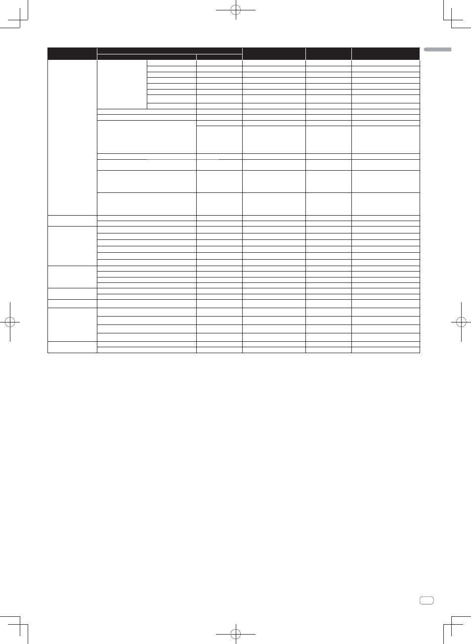
Category
Button/Control/Switch
MIDI assignment
Trigger/Toggle
Transmitted data
Name
Type
BEAT EFFECTS
CH SELECT
CH1
Switch
CC 034
2
OFF=0, ON=127
CH2
Switch
CC 035
2
OFF=0, ON=127
CH3
Switch
CC 036
2
OFF=0, ON=127
CH4
Switch
CC 037
2
OFF=0, ON=127
MIC
Switch
CC 038
2
OFF=0, ON=127
CF.A
Switch
CC 039
2
OFF=0, ON=127
CF.B
Switch
CC 040
2
OFF=0, ON=127
MASTER
Switch
CC 041
2
OFF=0, ON=127
MIDI LFO
Control
CC 118
—
0-127
QUANTIZE
Button
Note 118
Trigger/Toggle
—
TIME
Switch
CC 013
—
—
Switch
CC 045
—
TIME
value (When FLANGER,
PHASER
or FILTER is selected, the
value is halved. When a negative
value is selected, it is set to a posi-
tive value.)
LEVEL
/DEPTH
Control
CC 091
—
0-127
X-PAD
Control
CC 116
—
Sends the [X-PAD] position
information.
ON
/OFF
X-PAD
(touch)
When an effect other than [SND/RTN (MIDI
LFO
)] is selected at BEAT EFFECT
Button
CC 114
2
OFF=0, ON=127
ON
/OFF
X-PAD
(touch)
When
[SND/RTN (MIDI LFO)] is selected at
BEAT EFFECT
Button
CC 064
2
OFF=0, ON=127
MIC
HI
Control
CC 030
—
0-127
LOW
Control
CC 031
—
0-127
SOUND COLOR FX
NOISE
Button
CC 085
Trigger/Toggle
1
OFF=0, ON=127
SPACE
Button
CC 105
Trigger/Toggle
1
OFF=0, ON=127
GATE/COMP
Button
CC 106
Trigger/Toggle
1
OFF=0, ON=127
DUB ECHO
Button
CC 107
Trigger/Toggle
1
OFF=0, ON=127
CRUSH
Button
CC 086
Trigger/Toggle
1
OFF=0, ON=127
FILTER
Button
CC 087
Trigger/Toggle
1
OFF=0, ON=127
Fader Start
Fader Start 1
Button
CC 088
Trigger/Toggle
OFF=0, ON=127
Fader Start 2
Button
CC 089
Trigger/Toggle
OFF=0, ON=127
Fader Start 3
Button
CC 090
Trigger/Toggle
OFF=0, ON=127
Fader Start 4
Button
CC 093
Trigger/Toggle
OFF=0, ON=127
HEADPHONES
MIXING
Control
CC 027
—
0-127
LEVEL
Control
CC 026
—
0-127
Timing Clock
—
Timing Clock
—
—
Fader Start
operation
3
Channel fader 1 or crossfader
Note 102
—
BACK CUE = 0, PLAY = 127
Channel fader 2 or crossfader
Note 103
—
BACK CUE = 0, PLAY = 127
Channel fader 3 or crossfader
Note 104
—
BACK CUE = 0, PLAY = 127
Channel fader 4 or crossfader
Note 105
—
BACK CUE = 0, PLAY = 127
MIDI
START
Button
START
—
—
STOP
Button
STOP
—
—
1
When turning one button on switches another button from on to off, MIDI on and off messages are sent from the two buttons.
When there is no button that switches off, only the MIDI on message is sent from the button that was pressed.
2
When switched from one position to another position, the MIDI ON and OFF signals are sent respectively from both positions.
—
When the [START/STOP] button is pressed for over 1 second, MIDI messages corresponding to the positions of the buttons, faders and controls are sent in a bundle (Snapshot).
The MIDI Snapshot sends all MIDI messages other than MIDI start and MIDI stop.
3
Operation differs depending on the setting of the [CROSS FADER ASSIGN (A, THRU, B)] selector switch.
—
When the [CROSS FADER ASSIGN (A, THRU, B)] selector switch is set to [THRU]: MIDI messages are sent when the [FADER START] button is set to [ON] and the channel fader is moved away
from you from the nearest position towards you and when it is moved back to the nearest position towards you.
—
When the [CROSS FADER ASSIGN (A, THRU, B)] selector switch is set to [A]: MIDI messages are sent when the [FADER START] button is set to [ON] and the crossfader is moved from the far
edge of the [B] side and when it is moved back to the far edge of the [B] side.
—
When the [CROSS FADER ASSIGN (A, THRU, B)] selector switch is set to [B]: MIDI messages are sent when the [FADER START] button is set to [ON] and the crossfader is moved from the far
edge of the [A] side and when it is moved back to the far edge of the [A] side.