Buhler 65 Series User Manual
Page 31
65 Series Rotary Tiller
31
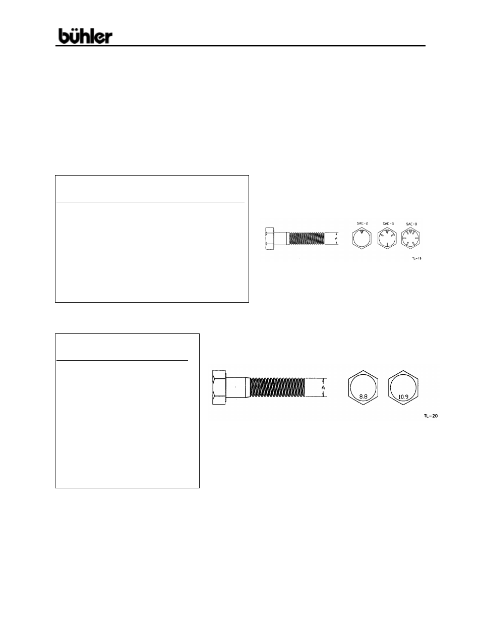
BOLT TORQUE
CHECKING BOLT TORQUE
The tables shown below give correct torque values for various bolts and capscrews.
Tighten all bolts to the torques specified in chart unless otherwise noted. Check
tightness of bolts periodically, using bolt torque chart as a guide. Replace hardware
with the same strength bolt.
ENGLISH TORQUE SPECIFICATIONS
Bolt
Bolt
Torque
*
Diameter SAE2
SAE 5
SAE 8
"A" N.m (lb-ft)
N.m (lb-ft)
N.m (lb-ft)
¼” 8 (6) 12 (9) 17 (12)
5/16"
13 (10)
25 (19)
36 (27)
3/8"
27 (20)
45 (33)
63 (45)
7/16"
41 (30)
72 (53)
100
(75)
½” 61 (45) 110 (80) 155 (115)
9/16"
95 (70) 155 (115)
220 (165)
5/8” 128 (95) 215 (160)
305 (220)
¾” 225 (165)
390 (290)
540 (400)
7/8" 230 (170)
570 (420)
880 (650)
1" 345 (225)
850 (630)
1320
(970)
METRIC TORQUE SPECIFICATIONS
Bolt
Bolt
Torque
*
Diameter 8.8 10.9
"A" N.m (lb-ft)
N.m (lb-ft)
M3
.5
(.4)
1.8
(1.3)
M4
3
(2.2)
4.5
(3.3)
M5
6
(4)
9
(7)
M6
10
(7)
15
(11)
M8 25 (18)
35 (26)
M10 50
(37)
70
(52)
M12
90
(66)
125
(92)
M14
140
(103)
200
(148)
* Torque value for bolts and cap screws are identified
M16
225
(166)
310
(229)
by their head markings.
M20 435 (321)
610 (450)
M24 750 (553) 1050 (774)
M30 1495 (1103)
2100 (1550)
M36 2600 (1917)
3675 (2710)
Torque figures indicated above are valid for non-greased or non-oiled threads and
heads unless otherwise specified. Therefore, do not grease or oil bolts or cap screws
unless otherwise specified in this manual. When using locking elements, increase
torque values by 5%.