Assign common, Assign 1–8, Assign common assign 1–8 – Boss Audio Systems Boss CDSM AMP EFFECTS PROCESSOR GT-100 User Manual
Page 32: Ctl/exp
CTL/EXP
32
ASSIGN COMMON
Parameter
Value
Explanation
INPUT SENS
0–100
This adjusts the input sensitivity when INPUT
LEVEL is selected for SOURCE .
ASSIGN 1–8
* If you want to light the ACCEL/CTL pedal’s LED indicator while the
ASSIGN 1–8 function is assigned to the ACCEL/CTL pedal, set the ACCEL/
CTL pedal FUNC (p . 31) to “LED ON/OFF .”
Parameter
Value
Explanation
OFF/ON
OFF, ON
Turns the ASSIGN 1–8 on/off .
SOURCE
EXP PEDAL
Assigns the GT-100’s [EXP] pedal .
EXP PDL SW
Assigns the EXP pedal switch .
P .LOOP PEDAL
Assigns the GT-100’s [PHRASE LOOP] pedal .
ACC/CTL PDL
Assigns the [ACCEL/CTL] pedal .
SUB EXP PDL
Assigns the external expression pedal (such as
the separately available EV-5) connected to the
SUB CTL 1, 2/SUB EXP jack .
SUB CTL1 PDL
Assigns the external footswitch (FS-5U, FS-6;
available separately) connected to the SUB CTL
1, 2/SUB EXP jack .
SUB CTL2 PDL
Assigns the external foot switch (FS-5U, FS-6;
available separately) connected to the SUB CTL
1, 2/SUB EXP jack .
INT PEDAL
Refer to “Virtual expression pedal system
(Internal Pedal / Wave Pedal)” (p . 35)
WAVE PEDAL
Refer to “Virtual expression pedal system
(Internal Pedal / Wave Pedal)” (p . 35)
INPUT LEVEL
The assigned target parameter will change
according to the input level .
CC#1–#31
Control Change messages from an external MIDI
device .
CC#64–#95
Control Change messages from an external MIDI
device .
SOURCE MODE
MOMENT
The normal state is Off (minimum value), with
the switch On (maximum value) only while the
footswitch is depressed .
TOGGLE
The setting is toggled On (maximum value)
or Off (minimum value) with each press of the
footswitch .
TARGET
CATEGRY
This selects the parameter to be changed .
Refer to TARGET list
TARGET
TARGET MIN
This sets the minimum value for the range in which the parameter
can change . The value differs depending on the parameter
assigned for TARGET parameter .
TARGET MAX
This sets the maximum value for the range in which the parameter
can change . The value differs depending on the parameter
assigned for TARGET parameter .
ACT RANGE LO 0–126
You can set the controllable range for target
parameters within the source’s operational
range . Target parameters are controlled within
the range set with ACT RANGE LO and ACT
RANGE HI . You should normally set ACT RANGE
LO to 0 and ACT RANGE HI to 127 .
ACT RANGE HI 1–127
WAVE RATE *1
0–100,
BPM –
This determines the time spend for one cycle of
the assumed EXP Pedal .
When set to BPM, the value of each parameter will be set accord-
ing to the value of the “MASTER BPM” specified for each patch . This
makes it easier to achieve effect sound settings that match the
tempo of the song .
* If, due to the tempo, the time is longer than the range of
allowable settings, it is then synchronized to a period either 1/2
or 1/4 of that time .
Parameter
Value
Explanation
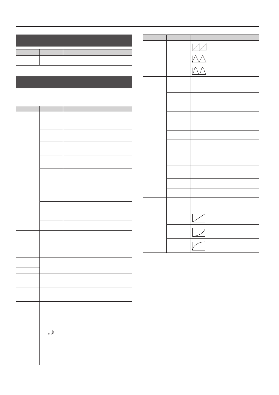
WAVEFORM *1
SAW
TRI
SINE
INT PDL
TRIGGER *2
PATCH CHANGE This is activated when a patch is selected .
EXP PDL-LO
This is activated when the GT-100’s [EXP] pedal is
set to the minimum position .
EXP PDL-MID
This is activated when the GT-100’s [EXP] pedal is
moved through the middle position .
EXP PDL-HI
This is activated when the GT-100’s [EXP] pedal is
set to the maximum position .
EXP PDL SW
This is activated when the EXP pedal switch is
operated .
P .LOOP PEDAL
This is activated when the [PHRASE LOOP] pedal
is operated .
ACC/CTL PDL
This is activated when the [ACCEL/CTL] Pedal is
operated .
SUB EXP PDL
This is activated when an external expression
pedal connected to the SUB CTL 1, 2/SUB EXP
jack is operated .
SUB CTL1 PDL
This is activated when an external footswitch
connected to the SUB CTL 1, 2/SUB EXP jack is
operated .
SUB CTL2 PDL
This is activated when an external footswitch
connected to the SUB CTL 1, 2/SUB EXP jack is
operated .
CC#1–#31
This is activated when a control change is
received .
CC#64–#95
This is activated when a control change is
received .
INT PDL TIME
*2
0–100
This specifies the time over which the internal
pedal will move from the toe-raised position to
the toe-down position .
INT PDL
CURVE *2
LINEAR
SLOW RISE
FAST RISE
*1 The WAVE RATE and WAVEFORM parameters are enabled when the Source
parameter is set to WAVE PEDAL .
*2 The INT PDL TRIGGER, INT PDL TIME, and INT PDL CURVE parameters are enabled
when the SOURCE parameter is set to INT PEDAL .