Installation, Configuring the axr-rf, Setting the dip switch – AMX RF Receiver AXR-RF User Manual
Page 7: Setting the rf validation level
Installation
3
AXR-RF RF Receiver
Installation
Configuring the AXR-RF
Use the eight-position DIP switch on, the rear of the AXR-RF, to set the device number. A device
number is assigned to devices connected to the AXlink bus. Every device on the bus must have a
unique device code. The device number must match the device assignment in the Axcess program.
AMX assigns device numbers in three groups:
!
Axcess Control Cards: 1 - 95
!
Axcess Bus Boxes: 96 - 127
!
Axcess Panels/Receivers: 128 - 255
Setting the DIP Switch
Locate the device DIP switch on the rear panel of the AXR-RF and set it to the desired binary
device number. The device number is set by the total value of DIP switch positions that are ON
(down).
Although the AXR-RF is a bus device, it should be numbered in the 128-255 range, because it is a
receiver.
Setting the RF Validation Level
An RF transmitter must send repetitions of data for the receiver to accept it as valid data. In some
installations, interference and physical structures may interfere with the receiver's ability to detect
the transmitted signal. The signal may become distorted. The receiver can be set to use either two or
three repetitions of sequential signals to validate and accept the signal data. To set the receiver's RF
level.
1.
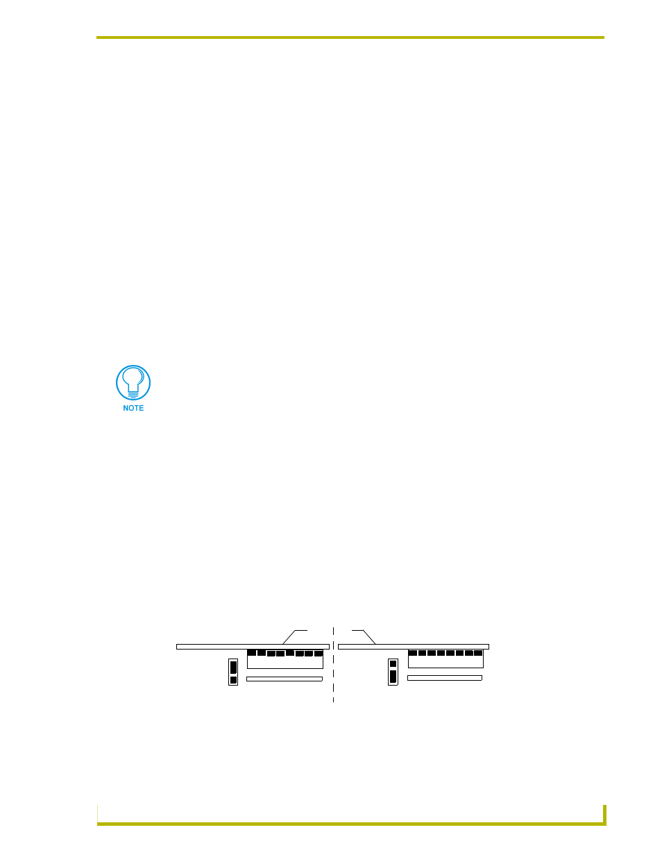
Locate jumper pins P3 (FIG. 1) on the circuit board.
2.
Position the P3 RF validation jumper to select the number of valid RF data repetitions to be
accepted:
If you change the device number, remove and reconnect the AXlink connector. This
enters the new device number into memory.
FIG. 1 RF validation jumper settings
P3
P3
Setting for 3 validations
Setting for 2 validations
Rear panel
DIP Switch
DIP Switch