Installing the cooker hood, Installing the cooker hood 16, Installation requirements – AEG X67453MD0 User Manual
Page 16: Unpacking
INSTALLING THE COOKER HOOD
16
��
���
���
��
���
����
���
��
��
���
����
�
���
���
���
��
��
���
�
��
���
���
��
�
����
��
���
���
��
���
INSTALLING THE COOKER HOOD
Please ensure that when the appliance is installed it is ea-
sily accessible to an engineer in the event of a breakdown.
All installations must comply with the local authorities
requirements for the discharge of exhaust air.
Incorrect installation may affect the safety of this
cooker hood.
Installation Requirements
Before installation check the wall to
which the cooker hood is to be fitted for
electric cables, water pipes or gas.
The chimney hood must be installed according to the
instructions suppliers below and by qualified and com-
petent personnel to the relevant National Standards.
The cooker hood is designed to be fixed to a solid block or block
wall over a cooking area. If not, suitable fixing must be used
for other types of walls. The hood can be used in the extraction
(ducted to the outside) or recirculation (internal recycling) mode.
The Installation work must be undertaken by a qualified and
competent person. The manufacturer disclaims any responsibility
to damages due to incorrect installation of
the cooker hood or if the cooker hood is not installed in
compliance with relevant regulations controlling this type of
installation.
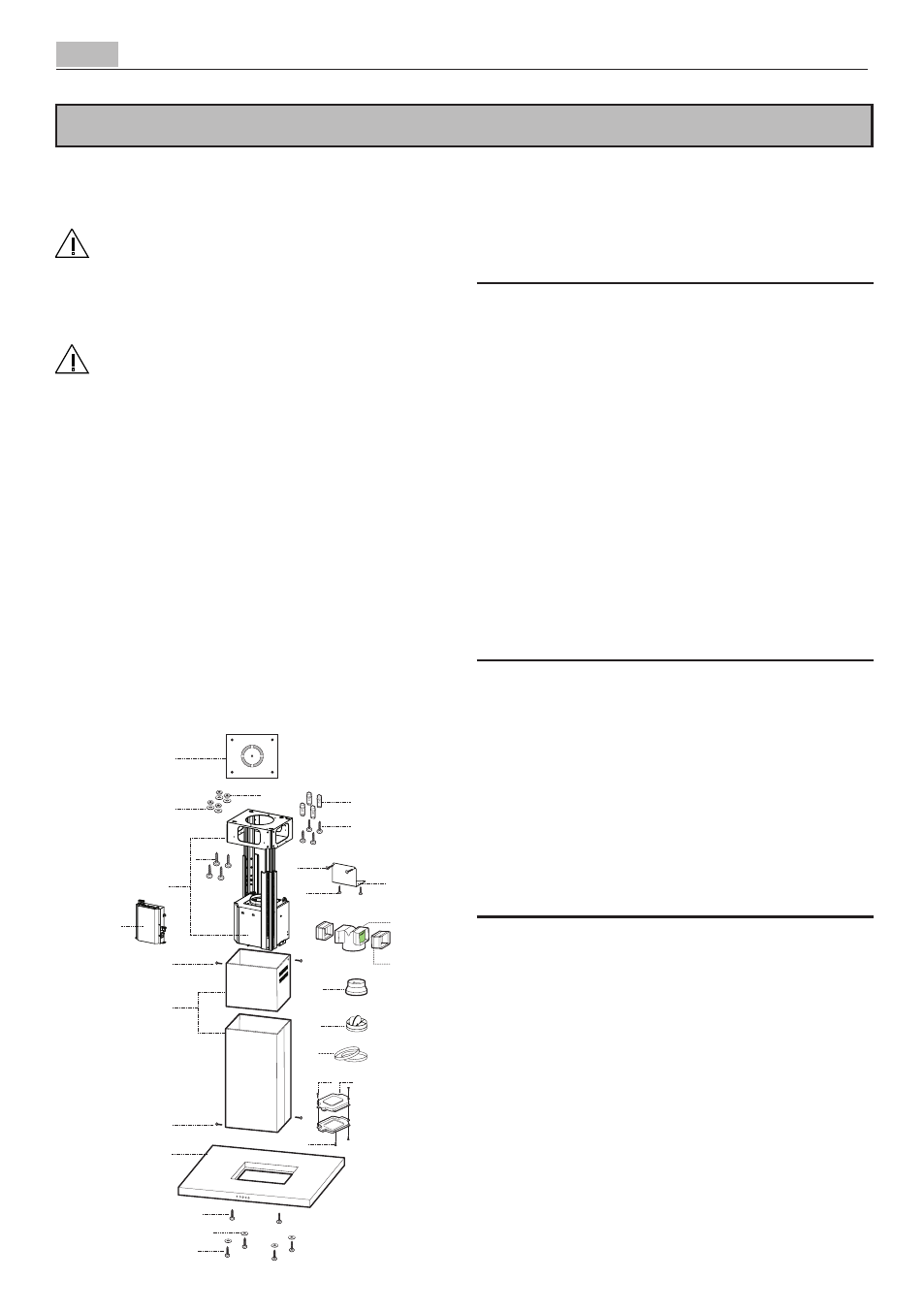
Unpacking
Before unpacking the cooker hood position the carton with the
arrows pointing upwards as illustrated on the carton.
The canopy is supplied with the following components for
installation:
Ref Qty Product Components
1
1
Hood Canopy complete with: Controls,
Lights, Filters
2
1
Telescopic chimney made up of:
2.1
1
Upper chimney
2.2
1
Lower chimney
7.1
1
Telescopic frame complete with Suction fan,
made up of:
7.1a 1
Upper frame
7.1b 1
Lower frame
9
1
Reduction flange ø 150-120 mm
10
1
Damper ø 150
14.1 2
Air Outlet Connection Extension
15
1
Air Outlet Connection
24
1
Connection box
25
Hose clamps (not included)
50
1
Control Board Group
Ref. Q.ty Installation components
7.3
1
Air Outlet Connection Support
11
4
Wall Plugs ø 10
12c
8
Screws 2,9 x 6,5
12e
4
Screws 2,9 x 9,5
12f
2
Screws M4 x 80
12g
4
Screws M6 x 80
12h
4
Screws 5,2 x 70
12q
4
Screws 3,5 x 9,5
21
1
Drilling template
22
8
6.4 mm int. dia washers
23
4
M6 nuts
Q.ty Documentation
1
Instruction booklet