Hitch assembly, Secure safety chain (2) around lower hitch frame, Hitch assembly -3 – Alamo SL60 User Manual
Page 81: Assembly, Assembl y
ASSEMBLY
SL60 03/07
Assembly Section 3-3
© 2007 Alamo Group Inc.
ASSEMBL
Y
3. Place bushing between both arms above
mower link and install 5/8” bolt through bush-
ing an fasten with 5/8” locknut.
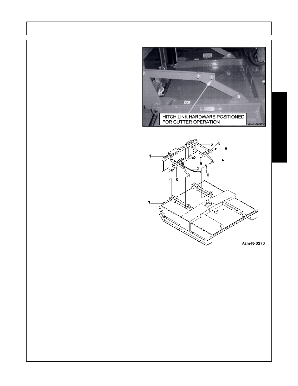
HITCH ASSEMBLY
1. Secure Hitch Weldment (1) to mower deck
using 1” x 5” Bolts (7) and 1” Locknuts (6).
2. Insert Bushing (5) in upper holes of hitch
weldment, place a set of Upper Floating LInks
(3) on each side of bushing, and secure
together using 5/8” x 1-3/4” Bolt (8) and 5/8”
Locknuts (9). Place bushing (5) between
opposite upper floating link set ends and
secure pairs together with bolt (8) and locknut
(9).
3. Place bushing (5) into end of Lower Floating
Links (4) and secure between upper links with
bolt (8) and locknut (9). Place another bushing
into opposite lower link hole and place against
outside of lugs near center of mower deck.
Insert bolt (8) through link, bushing, and lug,
and retain together with 5/8” Flat Washer (10),
and locknut (9).
4. Secure Safety Chain (2) around lower hitch
frame.
5. Tighten all bolts and nuts to the recommend
torque. (Refer to Image Asm-R-0270)