Mechanical installation – Alliance Laundry Systems UW50P-4 User Manual
Page 13
Installation
11
F232158
© Copyright, Alliance Laundry Systems LLC – DO NOT COPY or TRANSMIT
Mechanical Installation
A proper foundation is absolutely necessary for the
UW50P-4 due to its high extract speed and the G-force
exerted.
A bolt kit is available as an option consisting of eight
3/4 inch bolts, 8 inches long, which should be
imbedded in a reinforced concrete floor that is a
minimum of 12 inches thick.
Figure 1
Figure 2
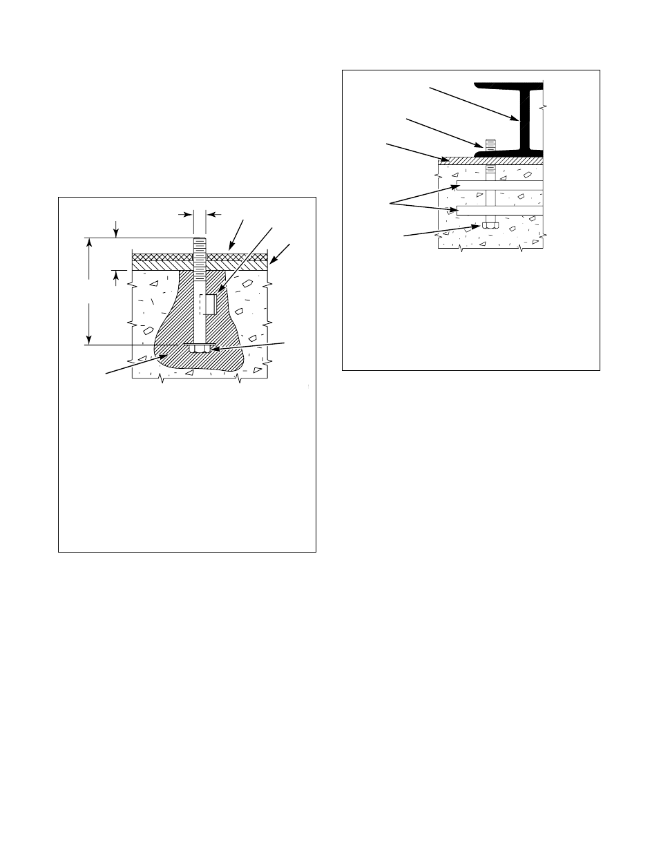
The threaded end of the bolts should extend 2 inches
above the surface of the floor. Refer to Figure 3 for the
location of these bolts. A bolt locator fixture (base
frame), consisting of a rigid welded assembly made of
reinforcing rod welded to the eight 3/4 inch bolts
which may be embedded in the concrete as one piece
is also available as an option. Refer to Figure 2. Be
sure the bolt threads also extend 2 inches above the
floor.
PHM178N
NOTE: Existing floor must be a minimum of 12 inches
thick.
1
Machine Base
2
Piece of Angle Welded to Bolt to Prevent
Turning
3
Grouting – 1/2 in. Thick
4
3/4 in.-10 x 8 in. Bolt
5
Conical hole drilled or chiseled into existing
floor. Fill with “Sulfaset” bolt or equivalent.
0.75 in.
(19 mm)
2 in.
(51 mm)
8 in.
(203 mm)
4
1
TYPICAL METHOD OF MOUNTING USING
INDIVIDUAL MOUNTING BOLTS
2
5
3
PHM179N
1
Machine Base
2
Bolt Threads
3
Grouting – 1/2 in. Thick
4
Reinforcing Rod
5
3/4 in. x 8 in. Bolt
PHM179N
1
2
3
4
TYPICAL METHOD OF MOUNTING
USING BASE FRAME
5