Lenovo G405s Notebook User Manual
Page 70
Lenovo G400s/G405s/G400s Touch/G500s/G505s/G500s Touch
Hardware Maintenance Manual
66
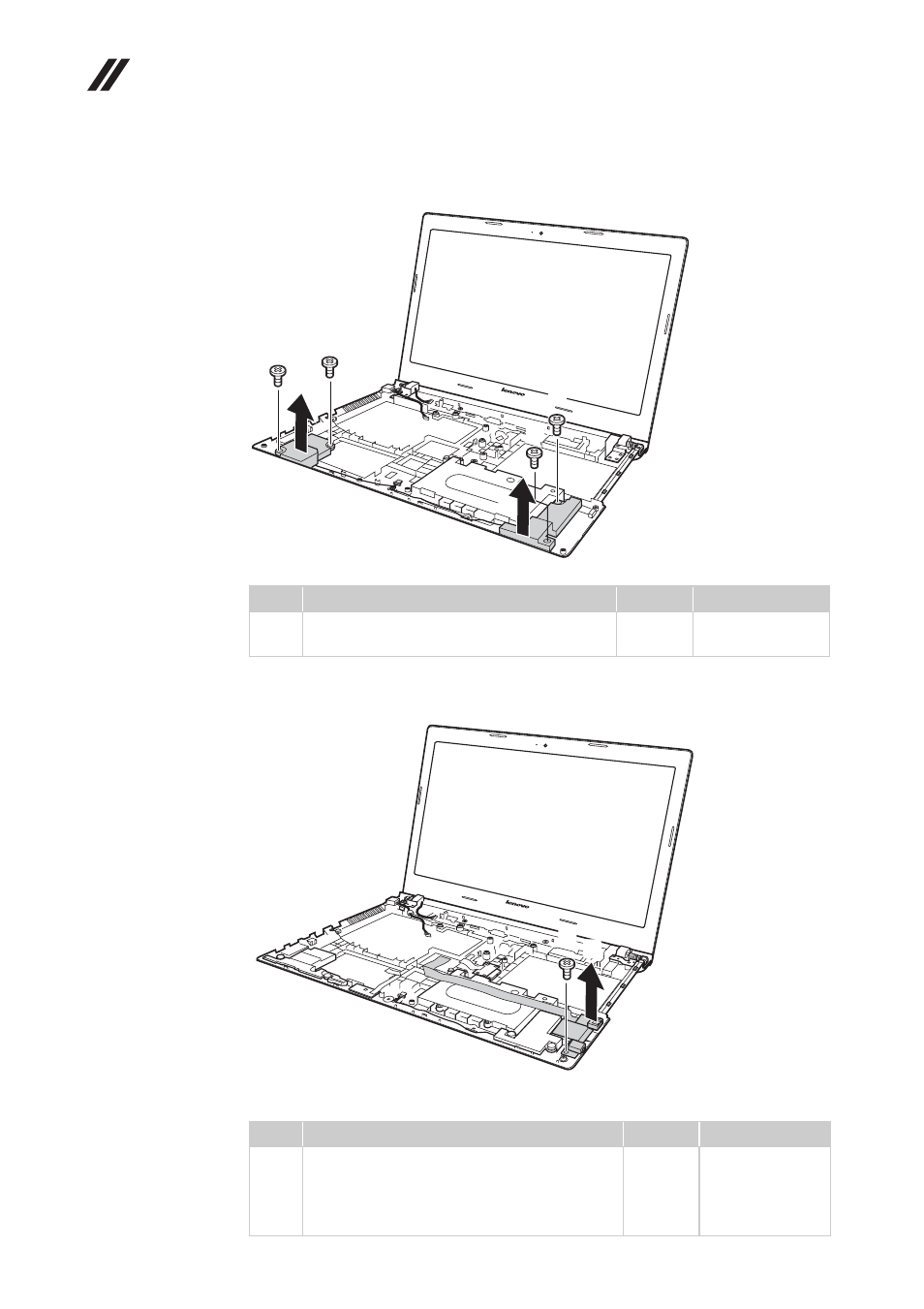
Figure 15. Removal steps of base cover, speakers, USB and power assembly (continued)
G400s:
G500s:
Loosen the screw
, then remove the USB board in the direction shown
by arrow
.
When installing:
Make sure that the USB board connector is attached firmly.
Step
Screw (quantity)
Color
Torque
M2.5 × 2 mm+5.7, flat-head, nylok-coated
(4)
Black
2.38 ~ 2.48 kgfcm
Step
Screw (quantity)
Color
Torque
M2.5 × 3 mm, flat-head, nylok-coated (1)
(G500s)
M2.5 × 4 mm, flat-head, nylok-coated (1)
(G400s)
Black
Black
2.38 ~ 2.5 kgfcm
a
a
a
a
b
b
a
b
c
b
c
c
This manual is related to the following products: