Asus AP130-D5 User Manual
Page 25
ASUS AP130-D5 Pedestal Server
25
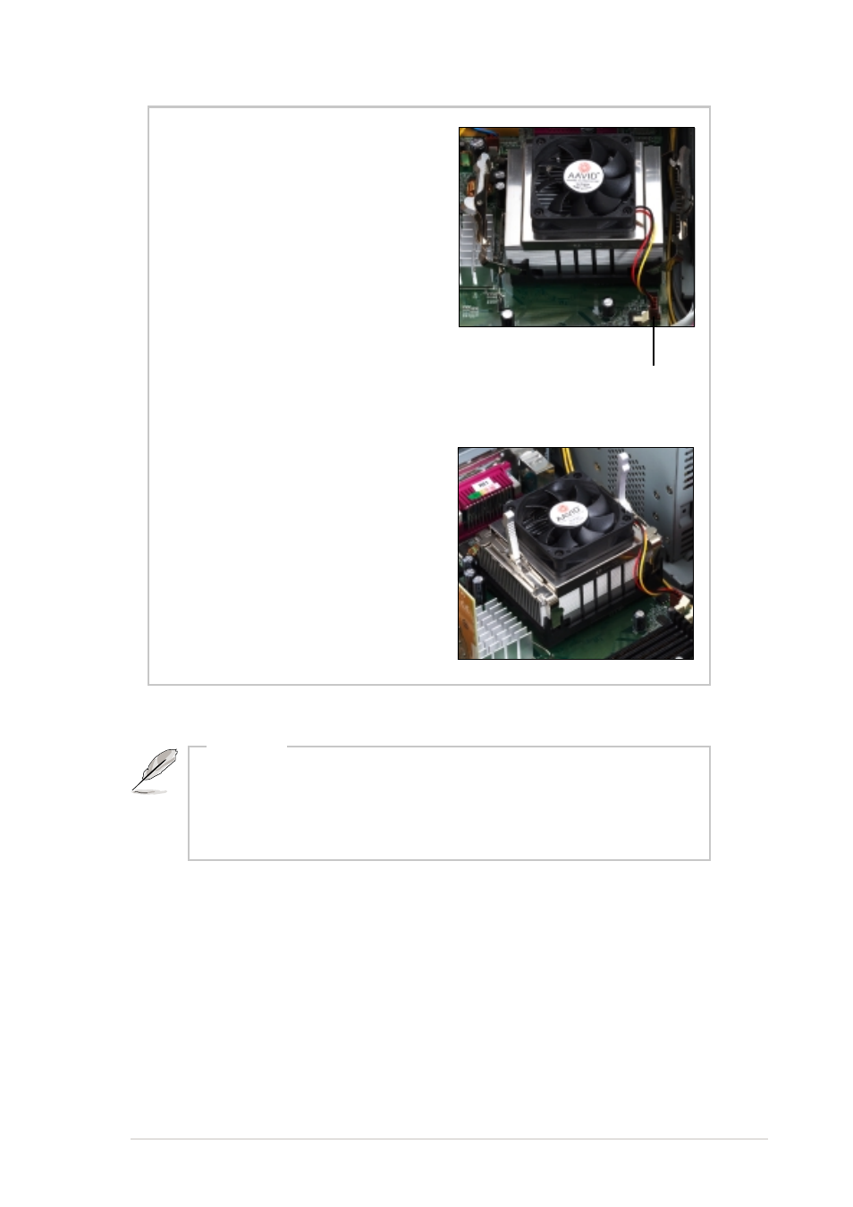
4. Orient the fan heatsink
assembly with the fan cable
nearest the CPU fan connector
on the motherboard (marked
CPU_FAN).
5. Carefully place the fan
heatsink assembly on top of
the CPU. Make sure that the
heatsink perfectly fits the
retention module base.
6. Connect the fan cable to the
CPU_FAN connector.
7. Flip back the retention brackets
inward so that they fit the sides
of the heatsink.
8. Simultaneously flip the bracket
levers 180° towards the arrows
until they click in place.
CPU fan connector
(CPU_FAN)
The fan heatsink assembly shown above is for reference only. The
fan heatsink assembly that you purchased may not look exactly
the same as shown. Refer to the documentation that came with
the fan heatsink assembly for more information.
NOTE
- CG8565 (410 pages)
- CG8565 (246 pages)
- CS5111 (26 pages)
- CS5120 (1 page)
- ET1611PUK (38 pages)
- S2-P8H61E (80 pages)
- P2-PH1 (80 pages)
- P1-P5945G (80 pages)
- P2-P5945GCX (90 pages)
- CG8270 (362 pages)
- CG8270 (218 pages)
- CG8270 (536 pages)
- CG8270 (72 pages)
- CG8270 (76 pages)
- CG8270 (534 pages)
- P3-P5G31 (100 pages)
- P3-PH4 (80 pages)
- P2-M2A690G (80 pages)
- P2-M2A690G (8 pages)
- P4-P5N9300 (82 pages)
- P4-P5N9300 (1 page)
- P1-P5945GC (92 pages)
- P2-P5945GC (92 pages)
- P3-P5G33 (98 pages)
- T3-P5945GC (80 pages)
- T3-P5945GCX (80 pages)
- P2-M2A690G (94 pages)
- T3-PH1 (80 pages)
- T3-PH1 (82 pages)
- T5-P5G41E (76 pages)
- T5-P5G41E (82 pages)
- S1-AT5NM10E (68 pages)
- P6-P7H55E (67 pages)
- ES5000 (174 pages)
- T4-P5G43 (104 pages)
- T-P5G31 (92 pages)
- BT6130 (60 pages)
- BT6130 (54 pages)
- BT6130 (2 pages)
- CG8265 (210 pages)
- CG8265 (350 pages)
- CM1740 (330 pages)
- CM1740 (70 pages)
- CM1740 (198 pages)
- P6-M4A3000E (59 pages)