Uni-lign, Ac-11 – Sheffer LA SERIES User Manual
Page 12
Reduces Misalignment
Problems!
Much effort has been made by many
to relieve, or eliminate the side
loading of cylinders created as a result
of misalignment. It is, of course,
almost impossible to get perfect
alignment and since the alignment of
the cylinder has a direct bearing on its
life, the efforts have been well worth
while.
A spherical bushing used by The
Sheffer Corporation and most
everyone else in the cylinder industry,
for various applications, is excellent
and serves a very useful purpose. It
does, however, have some very
definite limitations. First and
foremost among these is its inability,
with the limited space available, to
take the loads that the cylinder is
capable of producing. The second
deficiency of the spherical bushing or
bearing is that it is limited to a
maximum misalignment of five
degrees and can act as a complete
hinge in one direction only.
With the Sheffer UNI-LIGN most,
if not all, of these limitations have
been eliminated. For instance, fifteen
degrees each side of center is a
reasonable angular misalignment at
the pins, at the cylinder clevis and the
rod clevis, increasing by three times
the capabilities of the spherical
bushing, plus providing maximum
load carrying capabilities. It is
recommended that not more than a
thirty degree maximum angle be used
on the pins in the out-board end of
the UNI-LIGN units. However, when
lighter than maximum loads are
encountered, as much as 90 degrees
could be used with complete safety.
All components, pins, UNI-LIGN and
mounting brackets are designed to
take maximum loading of the cylinder
where pin sizes match that of the
clevis mount cylinder. All matching
accessories and clevis mounts for
cataloged cylinders are catalog
standard. Time saved in installation
may very well pay for the entire cost
of the application.
• No special fitting
• Gives freer range of mounting
positions
• Simplifies machine design
requirements
• Reduces cylinder binding and
slide-loading
• Allows universal swivel
• Less critical machining
• Reduces bearing and tube
wear
• Eliminates piston blow-by from
misalignment
• Works with standard mounting
accessories
Dimensions
FOR USE WITH SHEFFER
CLEVIS MOUNT
A & MH
HH
CLEVIS
SERIES
SERIES
UNI-
MOUNTING
ROD
CYLINDERS
CYLINDERS
LIGN
BRACKET
CLEVIS
BORE
BORE
PART
PART
PART
CD
ER
SIZE
SIZE
NO.
NO.
NO.
CB
PIN
RAD.
LR
U
1
1
/
8
1
1
/
8
UL-10
MBC-A30510
CLS-A2043
5
/
8
3
/
8
3
/
8
7
/
16
5
/
8
1
1
/
2
, 2
AND 2
1
/
2
1
1
/
2
UL-14
MBC-A40614
CLS-A1043
3
/
4
1
/
2
1
/
2
35
/
64
7
/
8
3
1
/
2
, 4
AND 5
2, 2
1
/
2
UL-19
MBC-A61020
CLS-A10750
1
1
/
4
3
/
4
3
/
4
51
/
64
1
3
/
16
6, 7
AND 8
3
1
/
4
UL-27
MBC-A81224
CLS-A11000
1
1
/
2
1
1
1
3
/
64
1
11
/
16
10
4
UL-38
MBC-A111632
CLS-A11250
2
1
3
/
8
1
3
/
8
1
7
/
16
2
3
/
8
12
5
UL-49
MBC-A142040
CLS-A11500
2
1
/
2
1
3
/
4
1
3
/
4
1
13
/
16
3
1
/
16
6
UL-58
†MBC-A142040
CLS-A11870
2
1
/
2
2
2
2
1
/
16
3
5
/
8
MBC-A162040
†For A SERIES
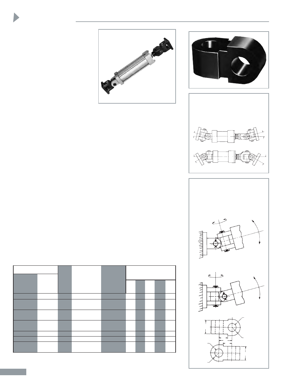
MOUNTING INFORMATION
15°
30°
B
B
CB
CD
ER
LR
U
LR
CB
CD
ER
A
A
B
A
A
B
30°
15°
Maximum recommended angular
deviation from center line:
INBOARD PIN-15°
OUTBOARD PIN-30°
A-A – PRIMARY PIVOT PLANE
(FOR AXIAL LOADING OF
CYLINDER)
B-B – SECONDARY PIVOT PLANE
(FOR MISALIGNMENT OF
CYLINDER)
CORRECT
INCORRECT
14
UNIVERSAL ALIGNMENT MOUNTING ACCESSORY
Uni-Lign
1
AC-11
DIMENSIONS