Front panel connector: jssi1 – MSI MS-96C8 Series User Manual
Page 30
2-16
MS-96C8 Server Board
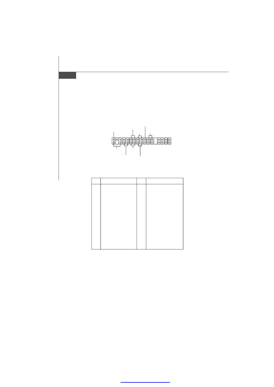
Front Panel Connector: JSSI1
The mainboard provides one front panel connector for electrical connection to the
front panel switches and LEDs.
Pin
Description
Pin
Description
1
Power LED +
2
+5VSB
3
Key
4
NC
5
Power LED -
6
NC
7
HDD Activity LED +
8
System Status LED +
9
HDD Activity LED -
10
System Status LED -
11
Power Switch+
12
LAN2 Activity LED +
13
Power Switch-
14
LAN2 Activity LED -
15
Reset Switch+
16
SMBus DAT
17
Reset Switch-
18
SMBus CLK
19
Buzzer+
20
Chassis Intrusion
21
Buzzer-
22
LAN1 Activity LED +
23
NMI to CPU Switch
24
LAN1 Activity LED -
25
Key
26
Key
27
ID LED+
28
SGPIO Clock
29
ID LED-
30
SGPIO Load
31
ID#
32
SGPIO Dataout 0
33
GND
34
SGPIO Dataout 1
JSSI1 Pin Definition
JSSI1
34
Standby
Power (5V)
Power LED
HDD
LED
Reset Switch
Power
Switch
Gigabit
LAN2 LED
Gigabit
LAN1 LED
SMBus
Chassis
Intruder
33
2
1
PDF created with pdfFactory Pro trial versi
- AM-690E (68 pages)
- IM-GM45 (73 pages)
- IM-GM45 (1 page)
- MS-7304 (52 pages)
- MS-6534 (109 pages)
- NVIDIA MS-7504PV (50 pages)
- G52-M6570XA-G22 (116 pages)
- RG300EX LITE (53 pages)
- MS-7242 (102 pages)
- CX700 (66 pages)
- GM965 (76 pages)
- G31M3 (96 pages)
- Fuzzy Mainboard GM965 (76 pages)
- 845 PRO2 (101 pages)
- FUZZY CX700 (82 pages)
- MS-7181 (107 pages)
- G45 (95 pages)
- FUZZY 945GM1 (83 pages)
- US54G (41 pages)
- MS-6566 (85 pages)
- MS-6380 (85 pages)
- MS-6575 (68 pages)
- IM-945GSE SERIES MS-9830 (83 pages)
- G52-S9617X1 (97 pages)
- G52-MA00628 (85 pages)
- MS-6523 (54 pages)
- ATX Motherboard G52-MA00362 (84 pages)
- N680GTX TWIN FROZR 4GD5/OC (1 page)
- N670 PE 2GD5/OC (1 page)
- N670GTX-PM2D2GD5/OC (1 page)
- N640GT-MD1GD3 (1 page)
- N630GT-MD4GD3 (1 page)
- N620GT-MD2GD3/LP (1 page)
- N610GT-MD2GD3/LP (1 page)
- N580GTX LIGHTNING XTREME EDITION (2 pages)
- N580GTX TWIN FROZR II/OC (2 pages)
- N560GTX-TI M2D1GD5/OC (2 pages)
- N560GTX-TI HAWK (2 pages)
- N560GTX-M2D1GD5 (2 pages)
- N460GTX-M2D1GD5/OC2 (2 pages)
- N460GTX HAWK TALON ATTACK (2 pages)
- N450GTS-MD1GD3 (2 pages)
- N440GT-MD1GD3/LP (2 pages)
- N430GT-MD1GD3/OC (2 pages)
- N220GT-MD1GD3/LP (2 pages)