Front panel connectors: jfp1, jfp2, Chasss intruson connector: jci1, Parallel port header: jlpt1 – MSI Z68MA-G45 (B3) Manual User Manual
Page 32
2-16
Hardware Setup
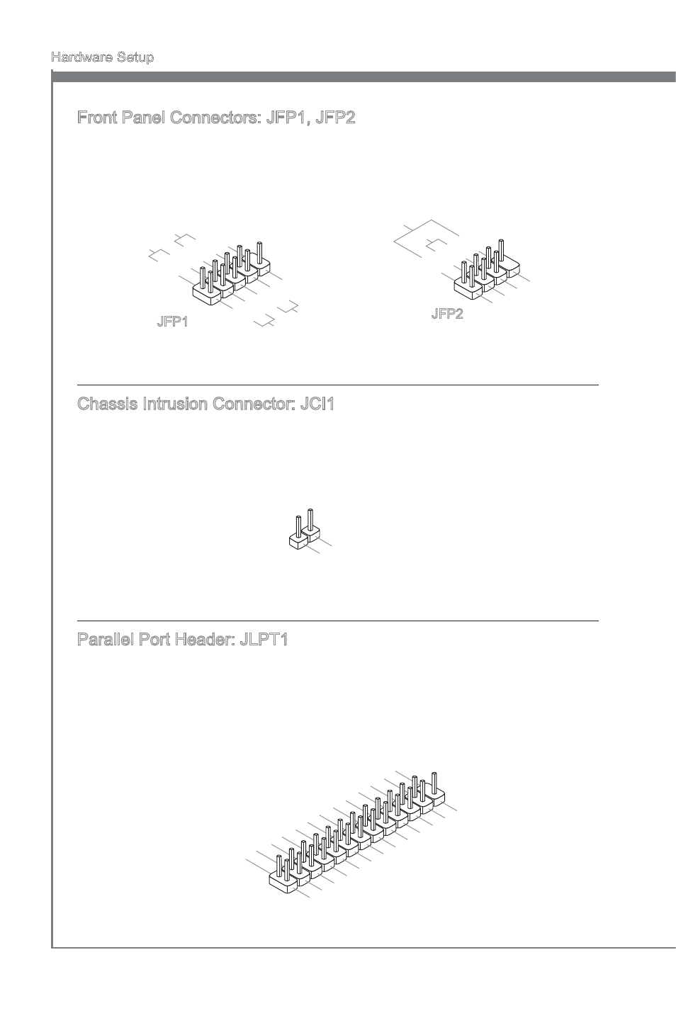
Front Panel Connectors: JFP1, JFP2
These connectors are for electrcal connecton to the front panel swtches and LEDs.
The JFP1 s complant wth Intel
®
Front Panel I/O Connectvty Desgn Gude.
1.Gro
und
3.Su
spen
d LE
D
5.Po
wer L
ED
7.No
Pin
8.+
6.-
4.+
2.-
Buzz
er
Spea
ker
1.+
3.-
10.N
o Pin
5.-
Rese
t Sw
itch
HDD
LED
Pow
er Sw
itch
Pow
er LE
D
7.+
9.Re
serve
d
8.-
6.+
4.-
2.+
JFP1
JFP2
Chasss Intruson Connector: JCI1
Ths connector connects to the chasss ntruson swtch cable. If the chasss s opened,
the chasss ntruson mechansm wll be actvated. The system wll record ths status
and show a warnng message on the screen. To clear the warnng, you must enter the
BIOS utlty and clear the record.
1.CIN
TRU
2.Gro
und
Parallel Port Header: JLPT1
Ths connector s used to connect an optonal parallel port bracket. The parallel port
s a standard prnter port that supports Enhanced Parallel Port (EPP) and Extended
Capabltes Parallel Port (ECP) mode.
10.G
roun
d
14.G
roun
d
8.LP
T_S
LIN#
12.G
roun
d
6.PIN
IT#
4.ER
R#
2.AF
D#
24.G
roun
d
22.G
roun
d
26.N
o Pin
20.G
roun
d
18.G
roun
d
16.G
roun
d
1.RS
TB#
3.PR
ND0
5.PR
ND1
7.PR
ND2
9.PR
ND3
11.P
RND
4
13.P
RND
5
15.P
RND
6
17.P
RND
7
19.A
CK#
21.B
USY
23.P
E
25.S
LCT