Howard HI-104 Single-Phase Pad Transformer User Manual
Page 33
Document 2.4.96, Revision 0
March, 2013
33
Single-Phase Pad-Mounted Compartmental-Type Distribution Transformers
2. Re-install the handhole cover. Re-install fasten-
ers according to the torque recommendations in
Table 1. After tightening all fasteners, re-torque
each one to ensure proper torque.
3. Pressurize the headspace to 3-4 PSIG and check
for fluid leaks. This pressure should be main-
tained for at least four hours, followed by another
leak check.
Torque Guidelines
Tables 1 through 4 below contain recommended
torque values for tightening various connections on
the transformer. Be aware that connections with gas-
kets and those involving rubber components (such
as high-voltage bushing inserts) will normally relax
after initial tightening.
Do not over-tighten any connection; otherwise,
gaskets might split due to over-compression, and
components might break. Fluid leaks could result if
tank-mounted components are over tightened. Check
with the Howard Industries Transformer Division for
recommended torque values for any devices or con-
nections not listed below. Use the manufacturer’s
recommended torque values for any user-provided
devices.
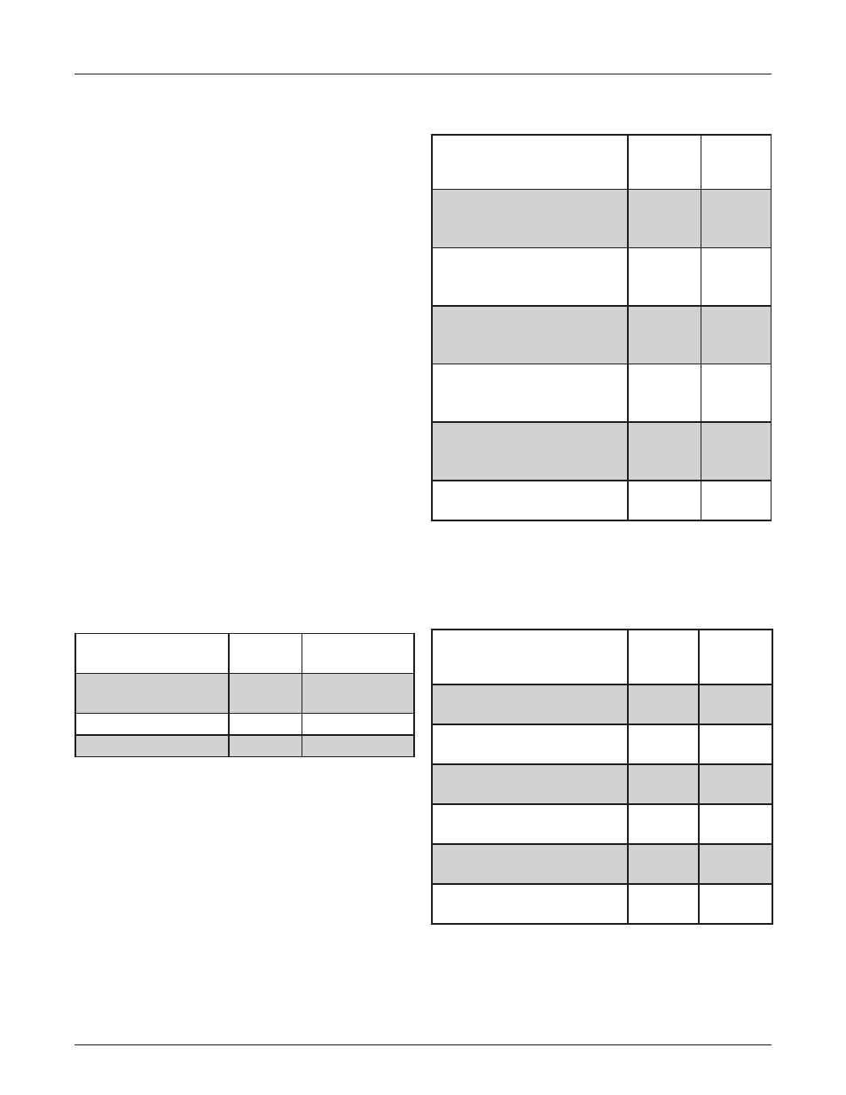
Table 1:
Torque Guidelines for External Cabinet Fasteners
Fastener Type
Nominal
Torque
Torque Range
(in-lbs)
Penta-head security
bolt
100
80-120
3/8” bolt
550
500-600
Hand-hole cover bolt
190
170-210
Table 2: Torque Guidelines for External Bushing
Mounting Hardware
Mounting Type
Nominal
Torque
(in-lbs)
Torque
Range
Low-voltage bushing, mold-
ed Tri-Clamp (without clamp
ring), 3/8” mounting studs
60
40-80
Low-voltage bushing, mold-
ed (with clamp ring), 3/8”
mounting studs
120
90-150
Low-voltage bushing, porce-
lain (with clamp ring), 1/2”
mounting studs
80
70-90
High-voltage bushing, mold-
ed Tri-Clamp (without clamp
ring), 3/8” mounting studs
60
40-80
High-voltage bushing,
molded (with clamp ring),
3/8” mounting studs
120
90-150
High-voltage bushing, por-
celain
80
70-90
When checking tightness of gasketed components, the measured
torque will normally be less than the nominal torque listed in the table
above due to relaxation of the gasket material. Additional tightening of
bushing mounting hardware may cause the component to crack or the
gasket to become over-compressed.
Table 3: Torque Guidelines for External Bushing
Terminal Connections
Terminal Type
Nominal
Torque
(in-lbs)
Torque
Range
High-voltage molded bush-
ing insert
180
170-190
High-voltage porcelain bush-
ing eye-bolt
210
180-240
High-voltage porcelain bush-
ing end cap
168
156-180
Low-voltage bushing, 5/8”
jam nut
600
480-720
Low-voltage bushing, 1” jam
nut
600
480-720
Low-voltage bushing, 1-1/4”
jam nut
720
600-840
Apply silicone grease before installation according to the insert manu-
facturer’s instructions.
When checking tightness of gasketed components, the measured
torque will normally be less than the nominal torque listed in the table
above due to relaxation of the gasket material. Additional tightening of
bushing mounting hardware may cause the component to crack or the
gasket to become over-compressed.