Howard Voltage Regulators User Manual
Page 5
SVR-1 Single-Phase Step Voltage Regulators
28-10
Copyright © 2011 Howard Industries, Inc.
5
Document No. 2.4.132
Revision: 0
Issued: October, 2011
Howard Industries, Inc.
Laurel, MS 39440
www.howardtransformers.com
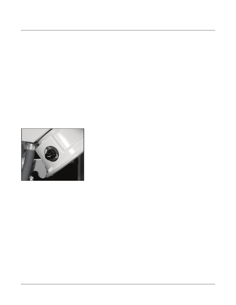
range. This is accomplished by setting
the raise (boost) and lower (buck) limit
switches (Figure 7) located on the tap
position indicator to prevent the tap
changer from traveling above or below
the desired settings. Scales on the
limit switches are graduated in percent
regulation, including 5%, 6-1/4%m
7-1/2%, 8-3/4% and 10% regulation
settings. Table 2 (Page 7) lists the load
current and regulation ranges available
with the HI-AMP
™
feature. At each
setting, a detent stop provides positive
adjustment. Upper and lower limits
need not be the same.
Upper and lower limits can also be
implemented with the digital control
unit.
_________________________________
SURGE ARRESTERS
Series Arrester
Each SVR-1 regulator is equipped
with an appropriately sized MOV-type
surge arrester connected between the
source and load bushings (Figure 4).
This series arrester (also known as a
bypass arrester) is provided to protect
the series winding of the regulator from
damage due to line surges, such as can
result from lightning, switching surges,
and line faults. The series arrester
alone does not provide complete
lightning protection. For more complete
protection, option shunt arresters
should be installed.
Shunt Arresters
MOV surge arresters are available as an
option on the SVR-1 regulator to provide
protection for the shunt winding. Shunt
arresters are mounted on the regulator
tank adjacent to the load bushing and
the source bushing. Each arrester
is connected between the bushing
terminal and ground.
FIGURE 7: HI-AMP
™
limit switches
(one located on each side of tap
position indicator)