Rotational sensor, Figure f – FMI STH/Q User Manual
Page 7
IN-ST431-14
7
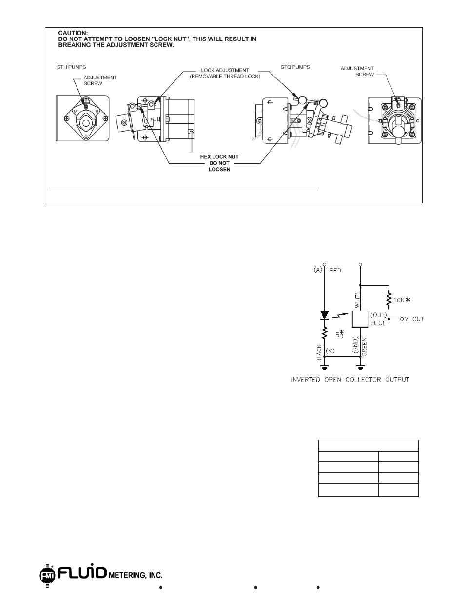
Figure E
NOTE:FOR ADDITIONAL REFERENCES SEE H431 AND Q431
Vcc
Vcc
* NOT SUPPLIED WITH OPTICAL SENSORS
See suggested Rd values table below.
Absolute Maximum Rating (T
A=
25ºC Unless otherwise noted)
Supply voltage, V (not to exceed 3 sec.).......................18 V
Input diode power dissipation....................................100 mW (1)
Output power dissipation............................................200 mW (2)
Total device power dissipation....................................300 mW (3)
Voltage at output lead (open collector output)............35 V
Diode foreword D.C Current............................................40 mA
Diode reverse D.C Voltage.............................................2 V
Note:
1. Derate linearly 2.22mW / ºC above 25ºC
2. Derate linearly 4.44mW / ºC above 25ºC
3. Derate linearly 6.66mW / ºC above 25ºC
4. The optical switches are terminated with 24 inches
of 26 A.W.G.,UL 1492 wire on each terminal.
Insulation colors and function are as follows:
Red-Anode, Black-Cathode, White-Vcc, Blue-Output,
Green-Ground
5. Normal application would be used with light source blocked,
simulated by I
F
=0mA
6. All parameters tested using pulse techniques.
7. Minimum supply voltage is 4.5 VDC
Figure F
Suggested R
D
Values
Vcc (VDC) R
D
(Ω)
5
180
12
470
15
620
Rotational Sensor
www.fmipump.com
800-223-3388
516-922-6050