5. assembly – Duff-Norton SK6405-100 User Manual
Page 6
translating tube (32).
14. Using 3/16 diameter punch drive pins (313) far
enough into the lifting nut (27) to just clear the translating
tube (32) wall. (Do not drive pins against OD of screw
(25).) Remove nut (27) with screw (25) from translating
tube (32).
15. Remove screw (25) from nut (27).
16. Remove pins (31) from nut (27) by driving pins (31)
remaining distance into ID of nut (27).
17. Remove stop pin (26) from screw (23).
18. Drive pin (34) from clevis end (35).
19. While restraining hex cap screw (28) from rotating,
remove clevis (35) from cap screw (28). (Cap screw can
be restrained from turning by using a 3/4 hex socket with
long extension into translating tube (32) ID.)
20. Remove lock nut (33) from cap screw (28).
21. Remove Belleville spring washers (30) and thrust
washer (29).
22. Remove cap screw (28), Belleville washers (30) and
thrust washer (29) from ID of translating tube (32).
23. Drive pin (4) from motor (3) shaft and remove coupling
(5) and remove damper (36) from I.D. of coupling. Note if
coupling is not damaged, it need not be removed.
24. A.C. unit - ball brake disassembly. Remove set
screws (7c) from ball housing (6) and remove springs (7b)
and balls (7a) and remove drive coupling (5) from ball
housing (6).
25. If bushing (16) in housing (13) is worn remove.
26. If bushing (14) in housing (13) clevis is worn, press
bushing (14) out.
27. If bushing (15) in housing (13) is worn, press bushing
out.
DISASSEMBLY IS COMPLETE.
4-5. Assembly:
1. A. Install damper (36) into coupling (5) I.D. and assem-
ble drive coupling (5) with hole in motor (3) shaft and
install pin (4).
B. A.C. Unit Only
I. Assemble ball housing (6) on drive coupling (5)
(line up ball cavities with groove in
coupling, assemble balls (7a), spring (7b) into
ball cavity and thread set screw (7c) into ball
housing (6), adjust set screws (7c) until torque
required to turn motor (3) shaft and coupling
(5) is 22 oz./in to 28 oz./in., while restraining ball
housing (6) from rotating. (note set screw (7c)
will be approximately flush with OD of ball hous-
ing (6).)
2. Assemble bearing (11) on pinion (12) and install retain-
ing ring (10) on pinion (12).
3. Apply Loctite retaining compound (or equal) to OD of
bushing (15) and install in housing (13) (assemble into
housing (13) end opposite side of housing with (4) holes
for mounting motor adaptor (9).
4. Press bushing (14) in housing (13) clevis.
5. Press bushing (16) in housing (13).
6. Install pinion (12) bearing (11), retaining ring (10) into
housing (13).
7. Assemble motor adaptor (9) onto housing (13) holding
in place with screws (8).
8. Press bushing (23) into outer tube (22).
9. Install seal (24) in outer tube (22) (seal scraper should
be facing inward).
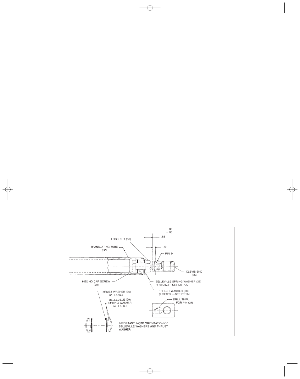
10. Apply a generous coat of Shell Darina EP2 grease to
thrust washer (30) and assemble thrust washer (30) and
Belleville washers (29) on hex cap screw (28) (see figure
4-1 for proper installation of washer).
FIGURE 2-1
SLIP CLUTCH ASSEMBLY
6405-100 10/10/06 11:50 AM Page 6