Specifications / 4. design and function, Design and function – WIKA TGT70 User Manual
Page 9
14047194.02 02/2013 GB/D/F/E
WIKA operating instructions model TGT70
9
GB
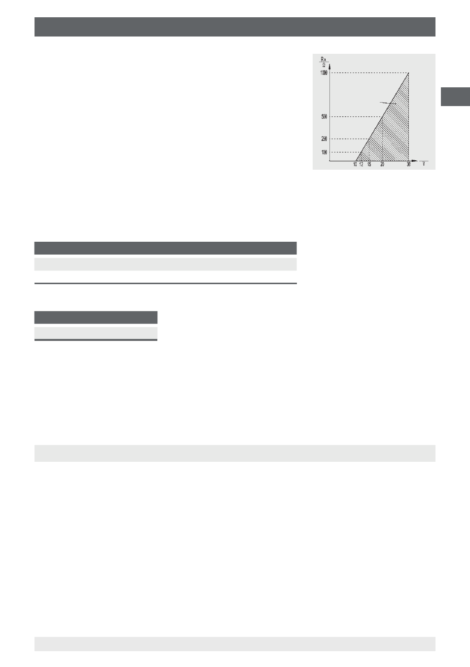
3.1 Output signal and permissible load
Voltage output (3-wire): R
A
> 5 kΩ
Current output (2-wire) 4 ... 20 mA:
R
A
≤ (U
SIG
- 10 V) / 0.02 A with R
A
in Ω and U
SIG
in DC V
3. Specifications / 4. Design and function
3.2 Electrical connection
Lateral terminal box, connector M12 or cable outlet
Pin assignment
Output signal
U
B+
U
B-
Signal
2-wire (current output)
1
2
-
3-wire (voltage output)
1
2
3
Wire colour (for cable outlet)
U
B+
U
B-
Signal
red
black
orange
Only operate the instrument with connecting cables that are shorter than 30 m. Do not
install the cables outside.
For further specifications see WIKA data sheet TV 18.01 and the order documentation.
4. Design and function
4.1 Description
The closed measuring system with liquid filling consists of a temperature sensor, a capillary
and a Bourdon tube. The volume change as a consequence of the heat applied to the
temperature sensor, and thus the pressure change in the closed system, is transmitted
through the capillary to the Bourdon tube and then indicated on the dial by an angular
deflection of the pointer shaft.
Through the combination of a mechanical measuring system and electronic signal
processing, the process temperature can be read securely, even if the power supply is lost.
U
SIG
Permissible range
4 ... 20 mA, 2-wire