Instruction manual ni-290e – WIKA PXA User Manual
Page 3
INSTRUCTION MANUAL
NI-290E
Rev. 0 01/05
6.1 PRELIMINARY OPERATIONS
Slide up the adjustment cover (Fig. 2, 1).
6.2 CALIBRATION CIRCUIT AND OPERATIONS
Prepare the control circuit as indicated in Fig.4.
The warning lamps should be connected to the terminals NA or
NC according to the required contact action.
If the instrument is equipped with two contacts, remember that
they are released simultaneously but within the specification
tolerance.
Connection between C and NA
• If the circuit is open at the working pressure, the instrument
closes the circuit when the set point is reached with pressure on
rise (closure on rise).
• If the circuit is closed at the working pressure, the instrument
opens the circuit when the set point is reached with pressure on
fall (opening on fall).
Connection between C and NC
• If the circuit is closed at the working pressure, the instrument
opens the circuit when the set point is reached with pressure on
rise (opening on rise).
• If the circuit is open at the working pressure, the instrument
closes the circuit when the set point is reached with pressure on
fall (closure on fall).
The test instrument should have a measurement range
approximately equal to or slightly wider than the pressure switch
range and should have an accuracy consistent with the precision
required to calibrate the set point.
The pressure switch must be kept in the normal installation
position, i.e. with the pressure connection downwards.
Modify the pressure in the circuit up to the desired microswitch set
point value.
Turn the adjusting bush using the adjustment rod until the relative
lamp turns on (or turns off); then turn it in the opposite direction
until the lamp turns off (or on). Slowly turn the bush again until the
lamp turns on (or off).
Fig. 4.
Calibration circuit
PS - Pressure switch
CA - Test gauge
V1 - Inlet valve
V2 - Discharge valve
P - Pressure source
Test fluid :
- air for
P
≤ 10 bar
- water for P
> 10 bar
Check the calibration value (varying the pressure in the circuit
accordingly) and register it, using a pen with indelible ink, on the
adhesive label.
6.3 FINAL OPERATIONS
Disconnect the instrument from the calibration circuit.
Close the adjustment slot by sliding down the slot cover (Fig. 2,
1), then seal with lead the instrument.
Mount on pressure connection the protecting cap supplied with
the instrument. It should be definitively removed only during the
connection steps.
7 - INSTRUMENT PLUMBING
The plumbing (see Fig. 2), aimed as a guarantee against possible
tampering of the calibration, can be carried out using a flexible
steel wire (2), 1 mm
2
in section, wound up around the case in the
groove purposely provided.
8 - MOUNTING AND CONNECTION S
8.1 MOUNTING
Mount the instrument directly on the pressure tap (Fig. 11) or on a
surface, through either a manifold (Fig.9) or a junction box (Fig.
10). If the optional bracket for surface or pipe mounting is used,
refer to NI-292E. The chosen position must be such that possible
shocks or temperature changes remain within tolerable limits.
With gas or vapour process fluid, the instrument must be
positioned higher than the pressure tap. With a liquid process
fluid, the instrument can be positioned higher or lower,
indifferently. In this case, during set point calibration the negative
or positive head must be taken into account.
8.2 PRESSURE CONNECTION
For a correct surface mounting (Fig. 9 and 10) proceed as follows.
Mount a shut-off valve with drain (root valve) on the pressure tap
to allow the instrument to be excluded and the connection tubing
to be drained. It is recommended that said valve has a capstan-
blocking device aimed at preventing it from being activated
casually and without authorisation.
Mount a service valve near the instrument to permit possible
functional verification on site. It is recommended that the service
valve is closed with a plug to prevent the outlet of the process
fluid caused by the incorrect use of said valve.
Mount a three piece joint onto the threaded attachment of the
instrument to permit the easy mounting or removal of the
instrument itself.
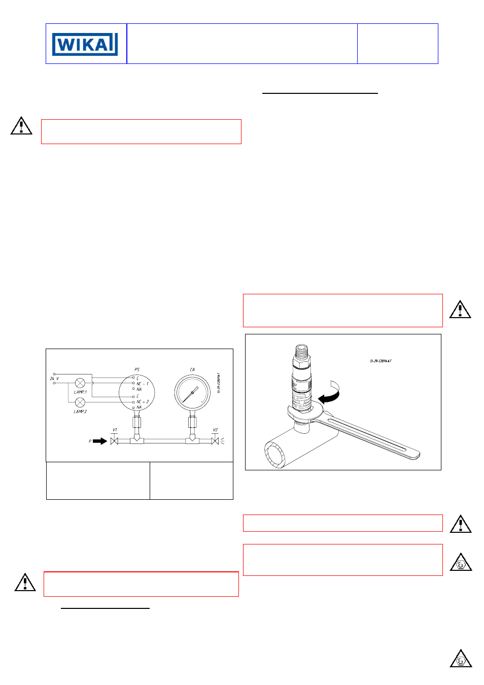
CAUTION: the pressure connection is to be tightened
applyIng the wrench ONLY on the hex of the pressure
attachment, NOT to the hex of the conduit connection, which
may cause the instrument NOT to work (Fig.5).
Fig. 5.
Pressure connection
Make use of a flexible tubing between instrument and pressure
tap so that, due to temperature changes, no mechanical stress be
applied to instrument connection.
Make sure that all the pressure junctions are leakproof. It is
important that there are no leakages in the circuit.
Close the root valve, the relative drain device and the service
valve fitted with safety plug.
8.3 ELECTRICAL CONNECTIONS
It is recommended to carry out the electrical connections
according to the applicable standards. In case of explosionproof
instruments (Series PXA and PXN) see also the standards EN-
60079-14 and EN 50281-1-2
The following mounting arrangements are possible.
8.3.1 MOUNTING WITH CABLE LOOSE
Run the cable so that it cannot be easily damaged (e.g. due to too
narrow bends, heat sources) and strain it.
Mount, if provided, the external ground device on the electrical
connection of the instrument. This device is to be threaded on,
while holding the electrical connection steady with a 27 mm
wrench on hex, until it reaches the bottom of the thread (Fig. 6).