Instruction manual ni-281e – WIKA PCA_HP User Manual
Page 3
INSTRUCTION MANUAL
NI-281E
Rev. 5 11/02
5.1 PRELIMINARY OPERATIONS
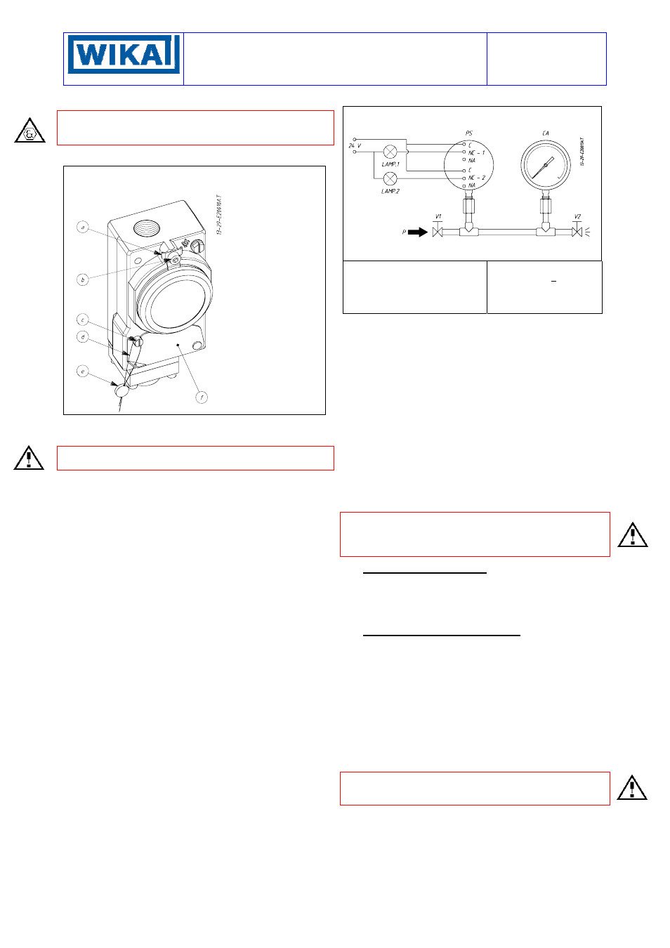
CAUTION: do not open the cover of explosionproof pressure
switches (Series PCA) when energized, in explosive
atmospheres.
With reference to Fig. 3 unscrew the screw (b) until the blocking
device (a) can be turned 180°; then unscrew the cover.
Fig. 3 -
Weatherproof pressure switch cover blocking
device and plumbing
a. Cover blocking
device
b. Blocking screw
c. Screw blocking
the adjustment
bush access
plate
d. Flexible steel
wire
e. Plumbing
f. Adjustment
bush access
plate
CALIBRATION CIRCUIT AND The warning lamps should be
connected to the contacts in the NA or NO position according to
the required contact action.
If the instrument is equipped with two microswitches, take into
account that they actuate simultaneously within rated tolerances.
The warning lamps can either be connected by means of a
thimble with a maximum diameter of 2.5 mm or by means of a test
plug with a diameter of 2 mm to be inserted in the appropriate
holes situated frontally beside the terminal screw (see Fig. 2).
Connection of C and NA terminals
• If the circuit is open at the working pressure, the switch closes
the circuit as the pressure increases when the desired values is
reached (MAX. closing).
• If the circuit is closed at the working pressure, the switch opens
the circuit as the pressure decreases when the desired value is
reached (MIN. opening).
Connection of C and NC terminals
• If the circuit is closed at the working pressure, the switch opens
the circuit as the pressure increases when the desired value is
reached (MAX. opening).
• If the circuit is open at the working pressure, the switch closes
the circuit as the pressure decreases when the desired value is
reached (MIN. closing).
The test instrument should have a measurement range
approximately equal to or slightly wider than the pressure switch
range and should have an accuracy consistent with the precision
required to calibrate the set point.
The pressure switch must be mounted in the normal installation
position, i.e. with the pressure connection downwards.
Avoid forcing the microswitch by hand or with tools. This could
affect the instrument functioning.
With reference to Fig.3, free the access to the adjustment bush by
loosening the screw (c) which holds the closure plate (f).
Increase the pressure in the circuit up to the desired microswitch
set point value.
Turn the adjustment bush using the adjustment rod with which the
instrument is equipped (Fig. 2) until the relative lamp turns on (or
turns off); then turn it in the opposite direction until the lamp turns
off (or on). Slowly turn the bush again until the lamp turns on (or
off).
Fig. 4 -
Calibration circuit
PS - Pressure switch
CA - Test gauge
V1 - Inlet valve
V2 - Discharge vale
P - Pressure source
Test fluid:
air for
P < 10 bar
water for
P > 10 bar
Check the calibration value (varying the pressure in the circuit
accordingly) and register it, using a pen with indelible ink, on the
ratings.
5.2 CALIBRATION USING REGULATION SCALE
See the specific instructions attached with instruments with this
option.
5.3 FINAL OPERATIONS
Disconnect the instrument from the calibration circuit.
With reference to Fig. 2, insert the adjustment rod into the
appropriate seat; close the access to the adjustment bush by
rotating the closure plate (4) and tighten the relative screw (6).
Take the cover, ensure that the sealing gasket is correctly fitted
into its seat, insert the cover onto the case and turn it clockwise
until the cover is closed.
With reference to Fig. 3 turn the blocking device (a) 180° sliding
the tongue into the appropriate seat in the cover; tighten the
blocking screws (b).
Mount on pressure connectionn and cable entry the protection
caps supplied with the instrument.
CAUTION: the protection caps should only be definitively
removed during the connection steps (see § 7).
6 - INSTRUMENT PLUMBING
The plumbing, aimed as a guarantee against possible tampering
of the calibrations, can be carried our using a flexible steel wire
(d) inserted into the holes in the screw (c) and the adjustment
bush closure plate provided for this purpose (see Fig. 3).
7 - MOUNTING AND CONNECTIONS
7.1 MOUNTING
Surface mount the instrument by mean of the holes, or pipe
mount using the appropriate bracket (see Fig. 8) or mount directly
on the plant in a vertical position (with the pressure connection
downwards). The chosen position must be such that the
possibility of shocks or temperature changes are within tolerable
limits. The above also applies to direct mounting. With gas or
vapour process fluid, the instrument must be positioned higher
than the pipe inlet (see Fig. 7). With a liquid process fluid, the
instrument can be positioned higher or lower, indifferently (see
Fig. 6 and 7). In this case, during set point calibration the
negative or positive head must be taken into account.
CAUTION: positions other than vertical are allowed provided
environmental conditions do not cause condensation to form or
water to enter the instrument through the ventilation path.
7.2 PRESSURE CONNECTIONS
For a correct installation it is necessary to:
Mount a shut-off valve with drain (root valve) on the process tube
to allow the instrument to be excluded and the connection tubing
to be drained. It is recommended that said valve has a capstan-
blocking device aimed at preventing it being activated casually
and without authorisation.
Mount a service valve near the instrument to permit possible
functional verification on site. It is recommended that the service