Installation in masonry or zero clearance chimney – DuraVent DirectVent Pro Chimney Liner System User Manual
Page 5
5
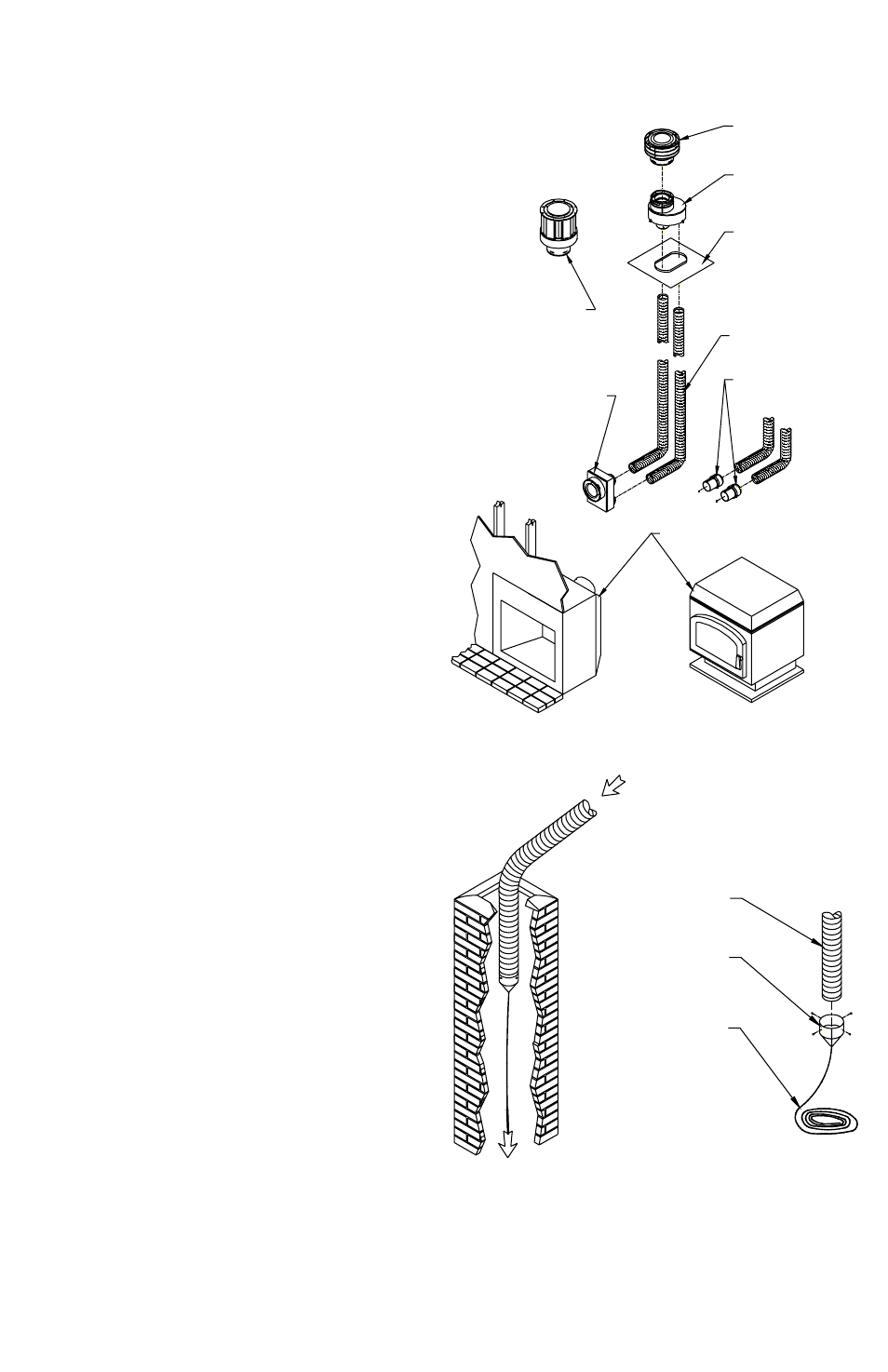
Figure 1
STANDARD
TERMINATION CAP
CO-LINEAR
TO CO-AxIAL
ADAPTER
BASEPLATE
FLEx LINER
CO-LINEAR FLEx
CONNECTORS
STOVE OR INSERT WITH EITHER
CO-AxIAL OR CO-LINEAR OUTLET
CO-AxIAL TO CO-LINEAR
APPLIANCE CONNECTOR
HIGH WIND
TERMINATION CAP
short, a flex coupler will be needed to attach
an additional length of Flex Liner to make up
the difference. If the flex length is too long,
the liner could sag below the appliance outlet
which could result in a potential fire hazard.
Note: For installation in a zero clearance
chimney, you must have at least a 7” I.D.
in order to run the two lines of Flex Liner
needed.
INSTALLATION IN MASONRY OR
ZERO CLEARANCE CHIMNEY
Step 1. Measure and record dimensions to
determine total Flex Liner length requirements
(see instructions below for details).
Step 2. Insert a rope through the end of the
Flex Puller and tie a knot at the end of the
rope. Attach the Flex Puller to the Flex Liner
using four sheet metal screws as shown.
(Figure 2) Carefully feed the liner down the
chimney (masonry or zero clearance) and out
through the damper. One person should feed
the liner through the chimney, and another
person should pull the liner from the bottom,
using the rope to guide the liner through to the
chimney bottom. Note: If additional lengths
of Flex Liner are needed span the chimney
height, use a Flex Coupling to connect the
pieces of Flex Liner together. Connect the
Flex to the Coupling by using four sheet metal
screws for each side. (Figure 3).
Step 3. After carefully feeding the Flex Liner
down the chimney to the bottom, form an
angle to line up the Flex Liner with the vent
opening on the appliance. Important: Do not
let the Flex Liner sag below the level at which
it will connect to the appliance or connector.
This could allow hot gas to become trapped
and potentially become a fire hazard. The Flex
Liner path should always be sloped up toward
the Termination Cap.
Step 4. Remove the Flex Puller from the Flex
Figure 2
FLEx LINER
FLEx PULLER
ROPE (NOT PROVIDED)