Type b gas vent liner system, Flex extensions – DuraVent DuraFlex AL Installation User Manual
Page 12
12
sealing the Top Plate to the masonry
chimney using the non-hardening
sealant, slide the B-Vent Storm Collar
over the length of B-Vent pipe, until
the proper length of pipe extends
above the chimney. Always have a
minimum of 12 inches of B-Vent pipe
below the Top Plate for stability. It is
preferable to extend the B-Vent pipe
down within the masonry chimney to
the roof line level so as to keep the
flue gas hot in the exposed portion
of the masonry chimney. Attach the
Storm Collar to the B-Vent pipe with
(4) 3/8-inch long sheet metal screws
equally spaced at 90°. The Storm
Collar rests on the Top Plate and
serves as the top support for the liner
system, and is UL Listed to support
up to 50 feet of Flex or B-Vent Liner.
Refer to Figure 17.
Step 4. Seal the Storm Collar to the
Top Plate and twist-lock the B-Vent top
to the B-Vent pipe. As an alternative
to the standard cap, you may want
to install a B-Vent High-Wind Top in
areas where excess wind may be a
concern (Figures 17 & 18).
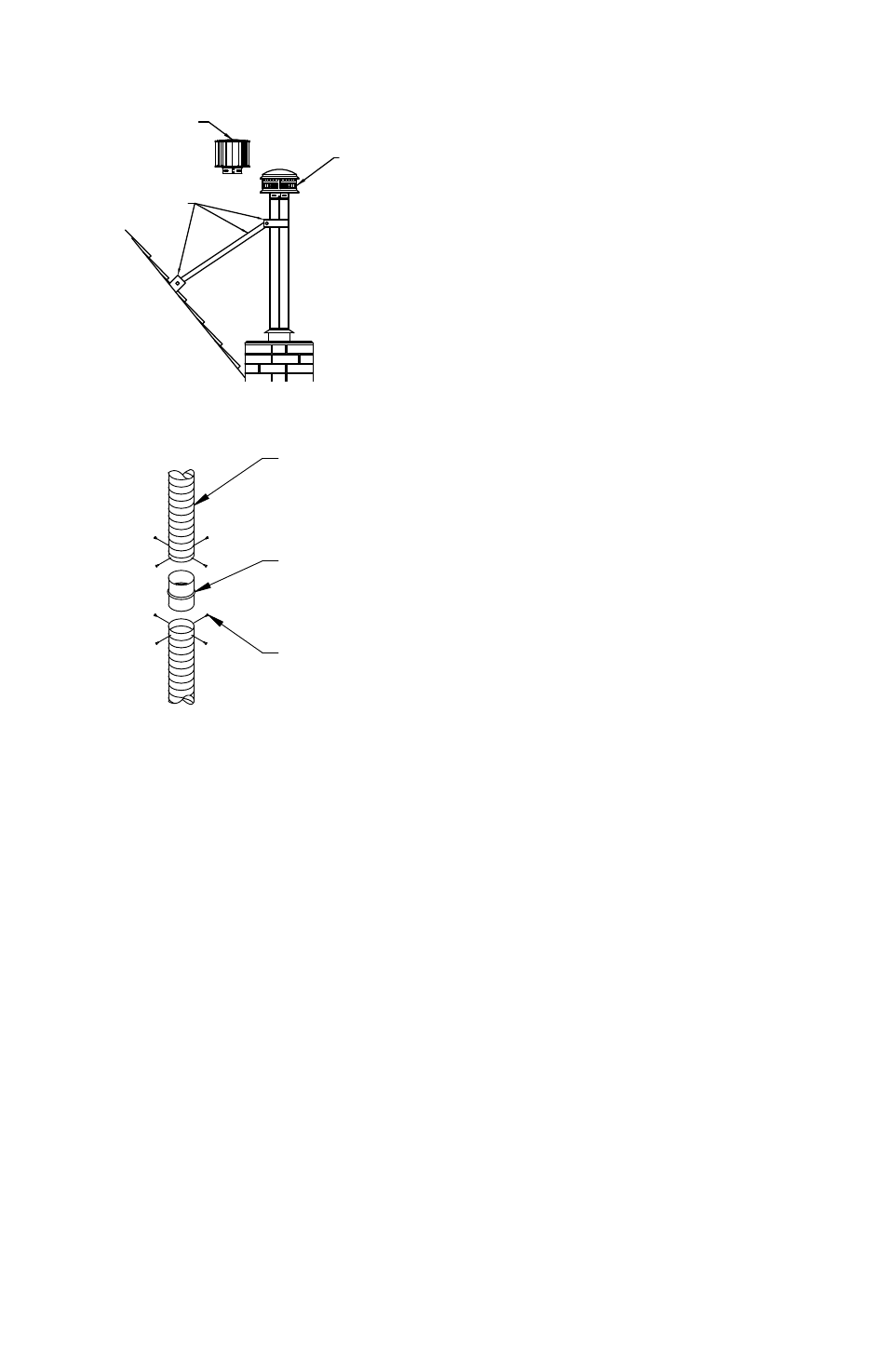
Step 5. For improved draft, the vent
may be extended in height above the
top of the masonry chimney by simply
adding additional lengths of B-Vent
Pipe. If the vent is more than 3 feet
above the top of the chimney, secure
it with a locally fabricated brace, as
shown in Figure 18.
TYPE B GAS VENT LINER SYSTEM
For exterior chimneys in cold
climates, an air insulated, double-
wall Type B Gas Vent Liner system
is recommended, particularly for
fan-assisted gas appliances, which
have a greater tendency to produce
corrosive condensation when flue
gases are permitted to cool in the
vent system. To install a 100% Type
B Gas Vent Liner, use a Type B Gas
Vent Termination and Pipe Lengths, in
combination with a Type B Gas Vent
Tee for this installation.
In the event that the exterior masonry
chimney has an offset, it will be
necessary to feed Flexible Liner down
through the offset, with Type B Gas
Vent to be used above the offset.
FLEX EXTENSIONS
For tall chimney installations where
more than one length of flex is
required, additional Flex may be
Figure 19
Figure 18
OPTIONAL HIGH
WINDCAP
STANDARD
CAP
SUPPORT
FLex LINeR
FLex COUPLING
SHeeT MeTAL
SCReWS