Installation into a masonry fireplace – DuraVent Multi-fuel venting system UL 641 User Manual
Page 9
9
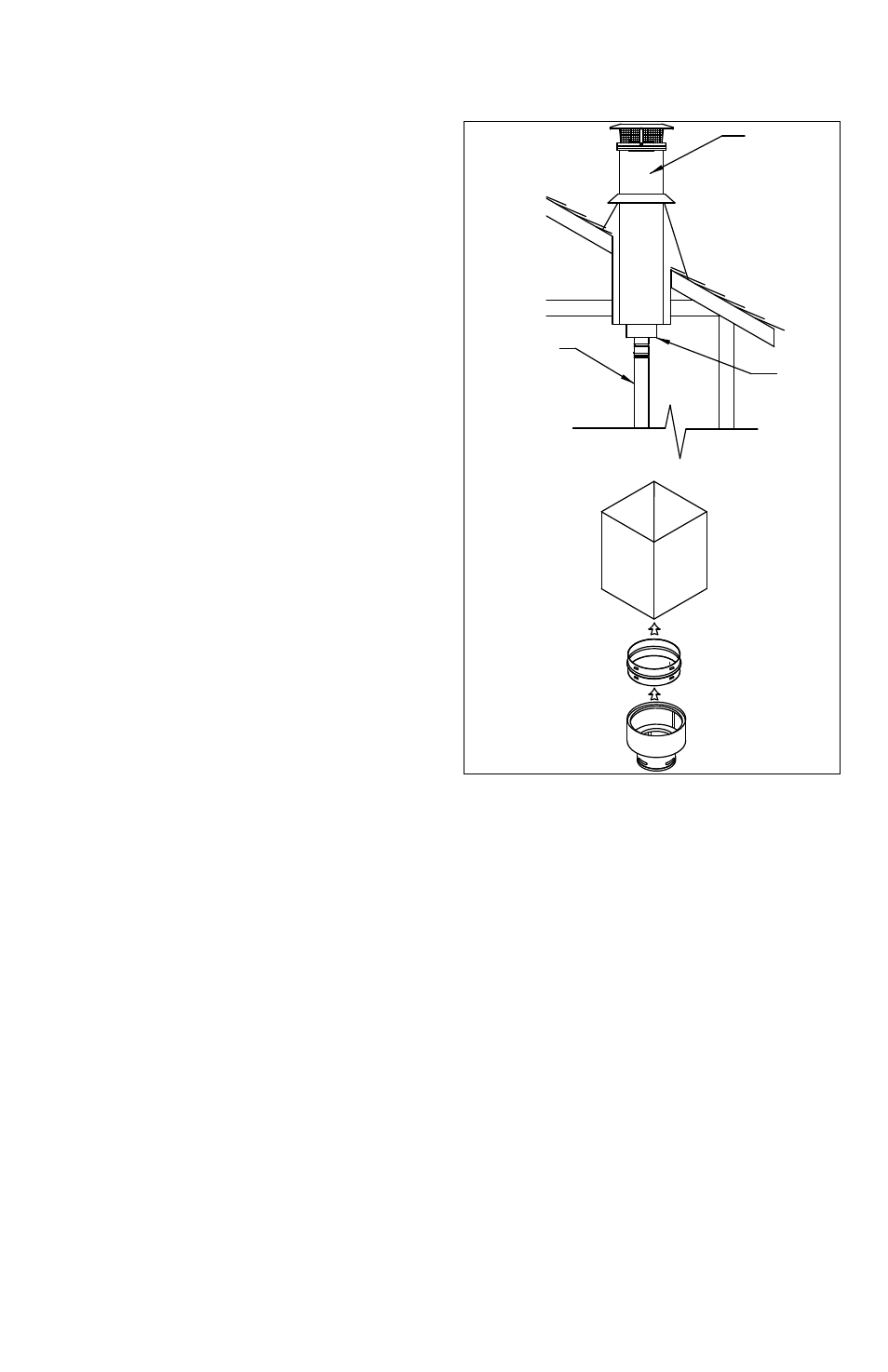
vertically plumb, then slip the Adjustable
Length up and twist lock it to the Chimney
Adapter. Once all the components are firmly
seated and properly aligned, carefully drill
three 1/8” diameter holes through the outer
sleeve only in the center of the slots located
at the bottom of the Adjustable Length
pipe. Do not penetrate the inner liner. Use
(3) 3/8” length sheet metal screws to secure
the Adjustable Length pipe. The completed
installation will look like
Figure 7.
INSTALLATION INTO A MASONRY
FIREPLACE
1. Have the masonry chimney inspected by
a certified chimney sweep or installer, to
determine it’s structural condition.
2. Carefully read the pellet stove or insert
installation instructions.
3. Measure and record the dimensions as
shown in Figure 8.
4. Use dimension “A” to determine total pipe
requirements. Add 12 additional inches
to insure the termination is an adequate
distance above the roofline.
5. The gross pipe required will be “A”
dimension plus 12". Five feet of this will be
Flex Pipe. The remainder will be rigid pipe.
For each joint, subtract 1-1/ 2" to allow for
the overlap. You may need extra pipe, or an
adjustable length pipe section to achieve the
correct height.
6. Assemble the first rigid pipe section to
the Flex Pipe, insuring that the “UP” arrows
shown on the pipe labels are, in fact, pointing
up. Push the sections together and twist to
lock. Screws are not required for a firm lock,
however, should it be desired to use them,
use stainless steel sheet metal screws 1/4"
long - DO NOT penetrate the inner liner of
the pipe.
7. Repeat this process for the remainder of
the pipe sections, and lower the assembly
down the chimney as shown in Figure 9.
Lower it below its normal position in order
to connect the Flex Pipe to the pipe on the
appliance. It may be necessary to tie a line to
the top section, to pull it back up later.
8. In making the connection at the appliance,
configurations other than the one shown in
Figure 10 may be made. It may be necessary
to contact the manufacturer of the unit to
determine exactly what may or may not be
done to make the correct connection. Some
typical arrangements are shown in Figures
11 and 12. A Pipe Adapter may be needed,
depending on the exit size of the stove or
insert collar.
9. If a Tee is necessary to make the
connection, as shown in Figure 12, the Tee
has a removable Clean Out Adapter on its
base to enable cleaning. The Tee Support
Figure 7
PELLET VENT
CHIMNEY
ADAPTER
DVL/DURABLACK
CHIMNEY ADAPTER
CHIMNEY
SUPPORT BOX
PELLET VENT
CHIMNEY
ADAPTER
EXISTING
DURATECH,
DURAPLUS, OR
DURACHIMNEY
SYSTEM
PELLET
VENT
SYSTEM