DuraVent Multi-fuel venting system UL 641 User Manual
Page 7
7
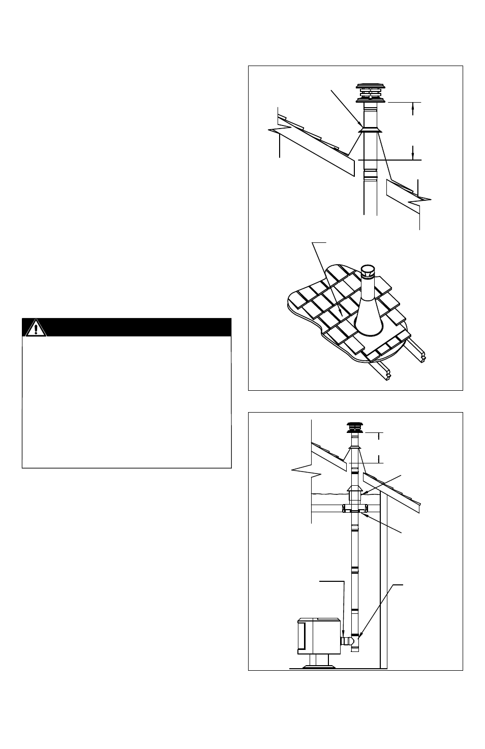
desired (Figure 6):
A. Place the appliance according to
manufacturer’s instructions.
B. Connect the Pipe Adapter to back of stove
and attach sufficient pipe to penetrate Wall
Thimble and extend at least 6” beyond the
exterior wall. You may install the optional
House Shield as shown in Figure 6. The
House Shield is used to protect the exterior
wall from vent discharge. Attach a Square or
Round Horizontal Cap. The Round Horizontal
Cap can be swiveled to be directed away
from nearby objects (fence, plants, etc.),
but must still be pointing in a generally
downward direction. Important: Horizontal
Caps must be pointed in a generally
downward direction to insure rain and snow
do not enter the cap, and cause potential
Figure 2
Figure 3
12 INCHES
MINIMUM
APPLY HIGH
TEMPERATURE
SEALANT COMPLETELY
AROUND TOP EDGE OF
STORM COLLAR
SHINGLES OVERLAP ON
TOP EDGE OF FLASHING
TEE WITH
CLEAN-OUT
ADAPTER
CEILING
SUPPORT/
FIRESTOP
SPACER
ATTIC
INSULATION
SHIELD
PIPE
ADAPTER
12” MIN
damage to the appliance. Either vent Cap
should be at least 6” from the wall.
C. Follow the below listed NFPA 211 rule for
distance of exit terminal from windows and
openings:
NFPA 211 (2003 ed.) Section 10.4 Termination:
10.4.5 (1) The exit terminal of a mechanical
draft system other than a direct vent
appliance (sealed combustion system
appliance) shall be located in accordance
with the following:
(a) Not less than 3 ft (.91m) above any forced
air inlet located within 10 ft. (3m).
(b) Not less than 4 ft. (1.2m) below, 4 ft. (1.2m)
WARNINg
WARNINg: Do not install any insulation
or other material inside the Wall
Thimble. Doing so can create a fire
hazard. The Wall Thimble requires the
created air clearance from the pipe
in order to make a safe installation.
However, building insulation may be
installed around the outside of the Wall
Thimble