Offset deviation, Offset chimney, Installation instructions – M&G DuraVent DuraTech® Canada User Manual
Page 8
8
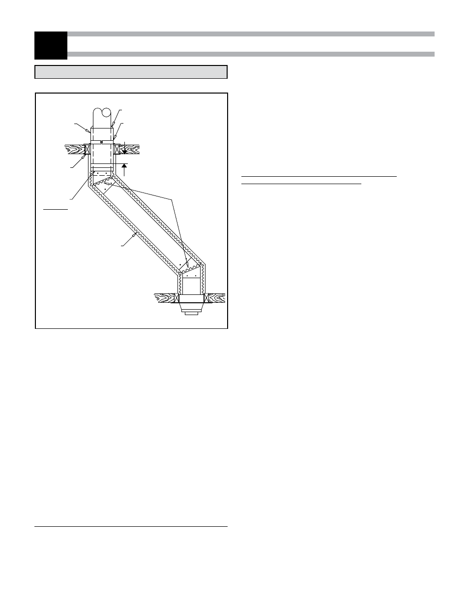
OFFSET DEVIATION
3
OFFSET CHIMNEY
If it is necessary to offset the chimney in order for it to pass through
an upstairs cupboard or to clear a joist, do this by using 15°, 30° or 45
insulated elbows. A maximum of two offsets (4 elbows in all) is allowed
in a chimney.
The minimum chimney height when using 15° offsets is 10’.
The minimum chimney height when using 30° offsets is 15’.
The maximum length of unsupported offset chimney is 6’. If the offset
chimney is longer than 6’, then it must be supported at 6’ intervals
using an offset support (DTC-RESU) or wall band (DTC-WSU). Or if a
Premium Shield is used then a Radiation Shield Connector (DTC-RSCI)
must be installed in the offset portion and attach to trusses with (2) two
plumbers straps.
INSTALLATION INSTRUCTIONS
If you are venting a Factory built fireplace or an oil or gas burning
appliance please refer to installation notes #2 (on page 5) for guidelines
on the use of the Premium shields.
For Unenclosed installation or venting of oil or gas appliances:
Put the first chimney length in the support. Turn it clockwise to lock it
in place.
Note: the male coupling must be on top.
RADIANT
SHIELD
CONNECTOR
(DTC-RSCI)
RADIANT SHIELD
CONNECTOR SUPPORT
(DTC-RSSR)
FLEXIBLE
SHIELD
(DTC-FLXS)
SWIVEL
ADAPTORS
OPTIONAL
(DTC-SA)
SPRING
SPACERS
RADIANT
SHIELD
CONNECTOR
FIRESTOP
(DTC-FRSC)
Figure 11
FLASHING COLLAR (DTC-SC)
1” MIN
Stack the next chimney length on the first length. Be sure that the male
and female threads are not in line when putting the lengths together. Turn
the chimney clockwise to lock it in place. You may add a 1/2in stainless
steel self tapping screw to prevent accidental unlocking. When you reach
the height at which the elbow will be installed:
Step 1. Install the insulated offset elbow on the vertical chimney length.
Turn it in the required direction and fasten it to the chimney with
the (4)-1/2" metal screws provided.
Step 2. Place the required offset chimney length (see chart below) on
the elbow. Turn it clockwise to lock it in place.
Step 3. Use another elbow to turn the chimney vertically. Again secure
the elbow to the chimney length using the (4)-1/2’’ metal screws.
For Enclosed installation (6", 7", and 8" dia. only)
(woodstove or coal burning appliance)
:
- Place the first chimney length on a flat surface with the male coupling
on top.
- Slide a flexible shield (DTC-FLXS) on top of that length all the way to
the bottom.
- Attach the flexible shield to the section using 3 x 1/2" stainless steel
self tapping screws.
- Slide this assembly in the support and turn clockwise to lock it in
place.
- At the ceiling level from the top, install a Radiation Shield Connector
(DTC-RSCI) and a Radiation Shield Support (DTC-FRSCS). Attach but
not tighten together yet (see Figure 13).
- Slide the Radiation Shield Connector down until the bottom of the
insulated tube exceed the bottom of ceiling.
Adjust the height until a minimum of (1”) of the Radiation Shield
Connector exceed the bottom of ceiling ( see Figure 11).
Stack the next chimney length on the first length. Be sure that the male
and female threads are not in line when putting the lengths together. Turn
the chimney clockwise to lock it in place. You may add a 1/2 in stainless
steel self tapping screw to prevent accidental unlocking.
When you reach the height at which the elbow will be installed:
Step 1. Install the insulated offset elbow on the vertical chimney length.
Turn it in the required direction and fasten it to the chimney with
the (4)-1/2’ metal screws provided.
Step 2. Place the required offset chimney length (see table 8) on the
elbow. Turn it clockwise to lock it in place.
Step 3. Use another elbow to turn the chimney vertically. Again secure
the elbow to the chimney length using the (4)-1/2" metal screws.
Attach a spacer spring around the chimney at each elbow to help keep
the flexible shield centered. (See figure 11) Slide the flexible shield up
the chimney and attach it below the ceiling to the Support Radiation Shield
using 3 self tapping metal screws. If you are limited in space to screw,
install a Swivel Adaptor (DTC-SA) (figure 11) below the Shield Connector
(DTC-RSCI) and one on the top end of the flexible shield.
In the attic:
• Fix the radiation shield to the chimney and tight the support collar.
• If the chimney is not enclosed in the attic, a storm collar (DTC-SC) must
be installed on top of Radiation Shield to prevent any loose insulation
from falling in the area between the chimney and the support.
• If the chimney is to be enclosed within the attic, continue installed
chimney sections up through the roof opening. Lower another
Telescopic Shield through the roof opening down onto the Radiation
Shield Connector.Adjust the height of the shield`s tube so it terminates
just above the roof opening but under the flashing.Once satisfied with
positioning, secure both ends of the shield using self-tapping screws.