M&G DuraVent DuraTech® Canada User Manual
Page 12
12
DTC-ISI
DTC-FSI
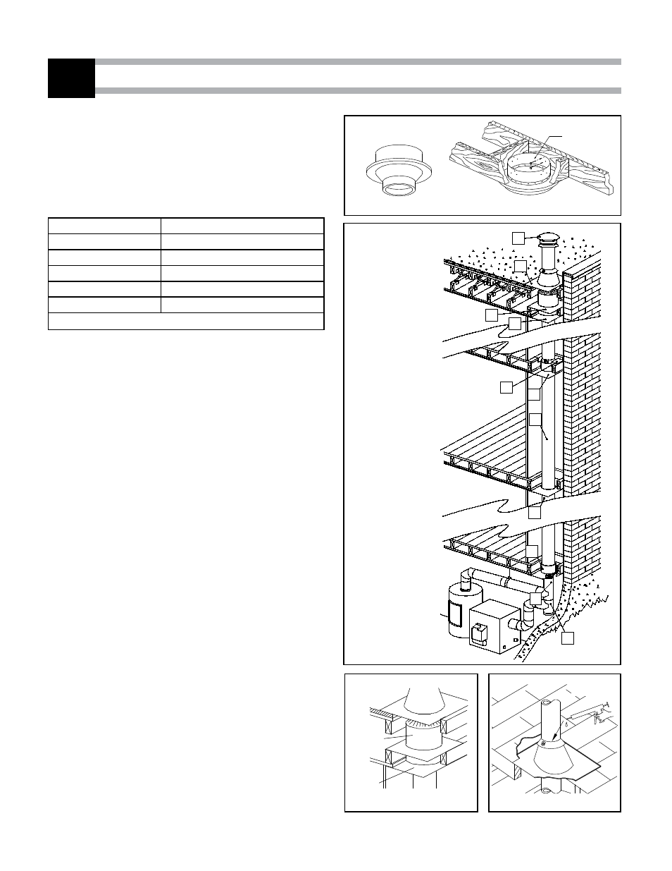
INTERIOR INSTALLATION ON A FURNACE AND WATER HEATER
5
Figure 21
Figure 22
Figure 23
Figure 24
Step 1. Locate the chimney in a convenient place as near as possible to
the appliance outlet. Cut and frame the holes in the floor, ceiling
and roof where the chimney will pass.
NOTE: It is important to follow the cutting dimensions for the
floor openings prescribed in this manual. This way, the holes left
by the folded positioning tab of the firestop (DTC-FS or DTC-ISI)
will be blocked by the ceiling.
Chimney Size
Hole size
5’’
12-1/8’’ x 12-1/8’’
6’’
12-1/8’’ x 12-1/8’’
7’’
14-3/8’’ x 14-3/8’’
8’’
14-3/8’’ x 14-3/8’’
10’’
14-3/8’’ x 14-3/8’’
Table 10
Step 2. From below push the support into the framed hole. Nail the
support to the framed box using (12) 3" spiral nails (see Figure
21).
Step 3. Put this first chimney length in the support. Turn it clockwise to
lock it in place.
NOTE: The male coupling must be on top.
Step 4. From below, install a firestop (DTC-FS) in each floor through
which the chimney passes (see Figure 22).
Step 5. Stack the next chimney length on the first length. Be sure that
the male and female threads are not in line when putting the
lengths together. Turn the chimney clockwise to lock it in place.
Continue until the required chimney height is reached.
Step 6. At the attic level, install a firestop (DTC-FS), from below and an
attic radiation shield (DTC-ISI) from above (see Figure 23).
Step 7. U.S. ONLY: Install the roof radiation shields in the roof joists.
These shields consist of four metal plates. Nail one plate to each
side of the joist using (2) 2-1/2’’ nails.
Step 8. Put the roof flashing in place. Seal the joint between the roof
and the flashing with roofing pitch.
For sloping roofs, place the flashing under the upper shingles
and on top of the lower shingles.
Nail the flashing to the roof using roofing nails.
Step 9. Place the storm collar over the chimney and the flashing. Tighten
it with the bolt supplied making sure the joint is properly caulked
(see Figure 24).
Fit the rain cap to the top of the chimney. Turn it clockwise to
lock it in place.
FINISH SUPPORT
(DTC-FSC) or (DTC-BS)
NAILS
9
8
7
4
6
4
5
4
3
1
2
1. C0NNECTOR
2. BASE TEE FOR
TWIN CONNECTIONS
3. FINISH SUPPORT
4. FIRESTOP
5. INSULATED LENGTH
6. ROOF SUPPORT
7. ATTIC RADIATION
SHIELD
8. FLAT ROOF FLASHING
9. REGULAR RAIN CAP
SILICONE
CAULKING