Figure 4: cat 5 pinout – Kramer Electronics PT-572HDCP+ User Manual
Page 13
10
PT-571HDCP/PT-572HDCP+ - Connecting the PT-571HDCP and
PT-572HDCP+ Transmitter Receiver Pair
6.1
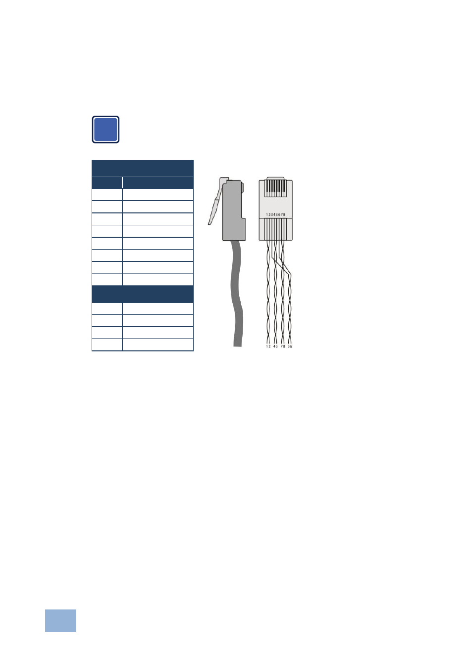
Wiring the CAT 5 LINE IN / LINE OUT RJ-45 Connectors
This section defines the CAT 5 pinout, using a straight pin-to-pin cable with RJ-45
connectors.
Note, that the cable Ground shielding must be connected / soldered to
the connector shield.
EIA /TIA 568B
Figure 4: CAT 5 PINOUT
PIN
Wire Color
1
Orange / White
2
Orange
3
Green / White
4
Blue
5
Blue / White
6
Green
7
Brown / White
8
Brown
Pair 1
4 and 5
Pair 2
1 and 2
Pair 3
3 and 6
Pair 4
7 and 8
i
This manual is related to the following products: