4 defining the pt-100 xga line extender, Recommendations for achieving the best performance, Defining the pt-100 xga line extender – Kramer Electronics PT-100 User Manual
Page 6: On 3.3, 4defining the pt-100 xga line extender
KRAMER: SIMPLE CREATIVE TECHNOLOGY
Defining the PT-100 XGA Line Extender
4
of the STP cable must be connected to a ground terminal on the units at both ends
(use the ground terminal of the power supply connection if necessary).
For a CAT 5 cable exceeding a distance of 50m, separate power supplies should be
connected to the transmitter and to the receiver simultaneously.
3.3
Recommendations for Achieving the Best Performance
To achieve the best performance:
• Use only good quality connection cables
to avoid interference, deterioration
in signal quality due to poor matching, and elevated noise levels (often
associated with low quality cables).
• Avoid interference from neighboring electrical appliances that may adversely
influence signal quality and position your Kramer transmitters away from
moisture, excessive sunlight and dust
4
Defining the PT-100 XGA Line Extender
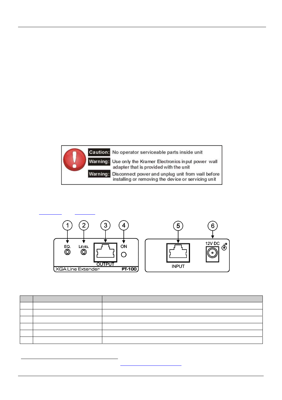
define the PT-100, XGA Line Extender.
Figure 1: PT-100, XGA Line Extender Front and Rear Panels
Table 1: PT-100, XGA Line Extender Front and Rear Panel Features
#
Feature
Function
1
EQ. Trimmer
Turn to adjust the line equalization
2
LEVEL Trimmer
Turn to adjust the line level
3
OUTPUT RJ-45 TP Connector
Connect to a compatible TP receiver (for example, VS-169TP or TP-122)
4
ON LED
Lights green when the device receives power
5
INPUT RJ-45 TP Connector
Connect to a compatible TP transmitter (for example, TP-121 or TP-125)
6
12V DC Power Connector
Connect to the 12V DC power adapter, center pin positive
1 Available from Kramer Electronics on our Web site at
http://www.kramerelectronics.com